
TB 9-6625-2315-24
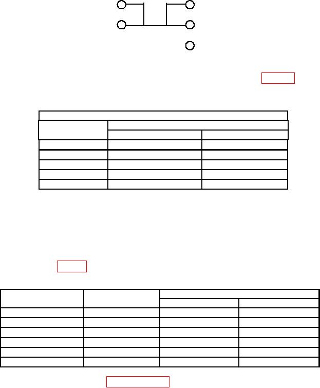
INPUT
4W SENSE
HI
HI
LO
LO
I
Figure 1. 4-wire short.
(3) Press RANGE/DIGITS or key to select ranges listed in table 3. If TI does
not indicate within limits specified, perform b below.
Table 3. DC V Zero Offset
Test instrument
Indications
Ranges
Min
Max
100
mV
-000.0035
mV
+000.0035
mV
1
V
-0.000007
V
+0.000007
V
10
V
-00.00005
V
+00.00005
V
100
V
-000.0006
V
+000.0006
V
1000
V
-0000.010
V
+0000.010
V
(4) Press Terminals Front/Rear pushbutton to Rear and repeat (3) above for rear terminals.
(5) Release Terminals Front/Rear pushbutton to Front.
(6) Disconnect short from TI front and rear input terminals.
(7) Connect calibrator OUTPUT HI and LO to TI front Input HI and LO.
(8) Press RANGE/DIGITS or key to select TI ranges and set calibrator output
for settings listed in table 4. If TI does not indicate within limits specified, perform b below.
Table 4. Dc Voltage
Test instrument
Calibrator output
Test instrument indications
ranges
settings (V dc)
Min
Max
100 mV
99.9915
mV
100.0085
mV
0.1
1V
0.999953
V
1.000047 V
1.0
10 V
9.9996
V
10.0004
V
10
10 V
-9.9996
V
-10.0004
V
-10
100 V
99.9949
V
100.0051
V
100
1000 V
999.945
V
1000.055
V
1000
b. Adjustments. Perform paragraphs 14 and 15 below.
6