
TB 9-6625-2339-24
(5) Press TI Single key. When sweep is finished, look for any residual responses at
or above TI display line.
(6) Press TI FREQUENCY and keys.
(7) Repeat technique of (5) and (6) above up to 6.7 GHz. Residuals will not be above
TI display line.
(8) Disconnect equipment setup.
b. Adjustments. None.
20. Power Supply
NOTE
Do not perform power supply check if all other parameters are
within tolerance.
a. Performance Check
(1) Press TI power STANDBY pushbutton.
(2) Disconnect TI power cord.
(3) Remove TI outer case and inner shield.
(4) Plug TI power supply test board into any available slot, except the slot for the
processor board.
(5) Connect TI power cord.
(6) Press TI power ON pushbutton.
(7) Observe LED's on power supply test board.
NOTE
Power supply test board LED's will be illuminated if voltages
are within 10 percent of their specified value.
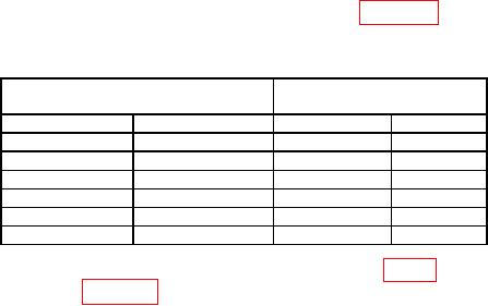
(8) Connect multimeter to test points as listed in table 23 and verify voltages are
within limits specified.
Table 23. Power Supply Voltages
Test instrument
indication (Vdc)
Test point
Common
Min
Max
15.22
14.78
TP4 or TP10
TP13 (ACOM)
5.07
4.93
TP5 or TP11
TP13 (ACOM)
TP3 or TP9
TP13 (ACOM)
4.93
5.07
TP2 or TP8
TP12 (DCOM)
5.1
5.3
TP1 or TP7
TP13 (ACOM)
14.78
15.22
TP6
TP13 (ACOM)
26.04
29.96
(9) Connect multimeter to TI probe power connector (fig. 5) and verify voltages are
within limits specified in table 24.