TB 9-6625-2340-35
b. Adjustments
(1) Remove top cover from TI.
(2) Press TI keys as listed in (a) through (i) below:
(a)
2-22 GHz.
(b)
CENTER FREQUENCY, 100, MHz.
(c)
FREQUENCY SPAN, 5, MHz.
(d)
RES BW, 3, MHz.
REFERENCE LEVEL, 10, -dBm.
(e)
(f)
SCALE LIN.
(g)
SHIFT.
AUTOA.
(h)
(i)
REFERENCE LEVEL.
(3) Adjust DATA knob to position trace at (or just below) reference level (top)
graticule line.
(4) Press TI keys as listed in (a) through (d) below:
(a)
MARKER NORMAL.
(b)
MARKER PEAK SEARCH.
MARKER→CF.
(c)
MARKER ∆.
(d)
(5) Using TI DATA knob adjust marker down the positive going side of the
displayed signal to the -3 dB point.
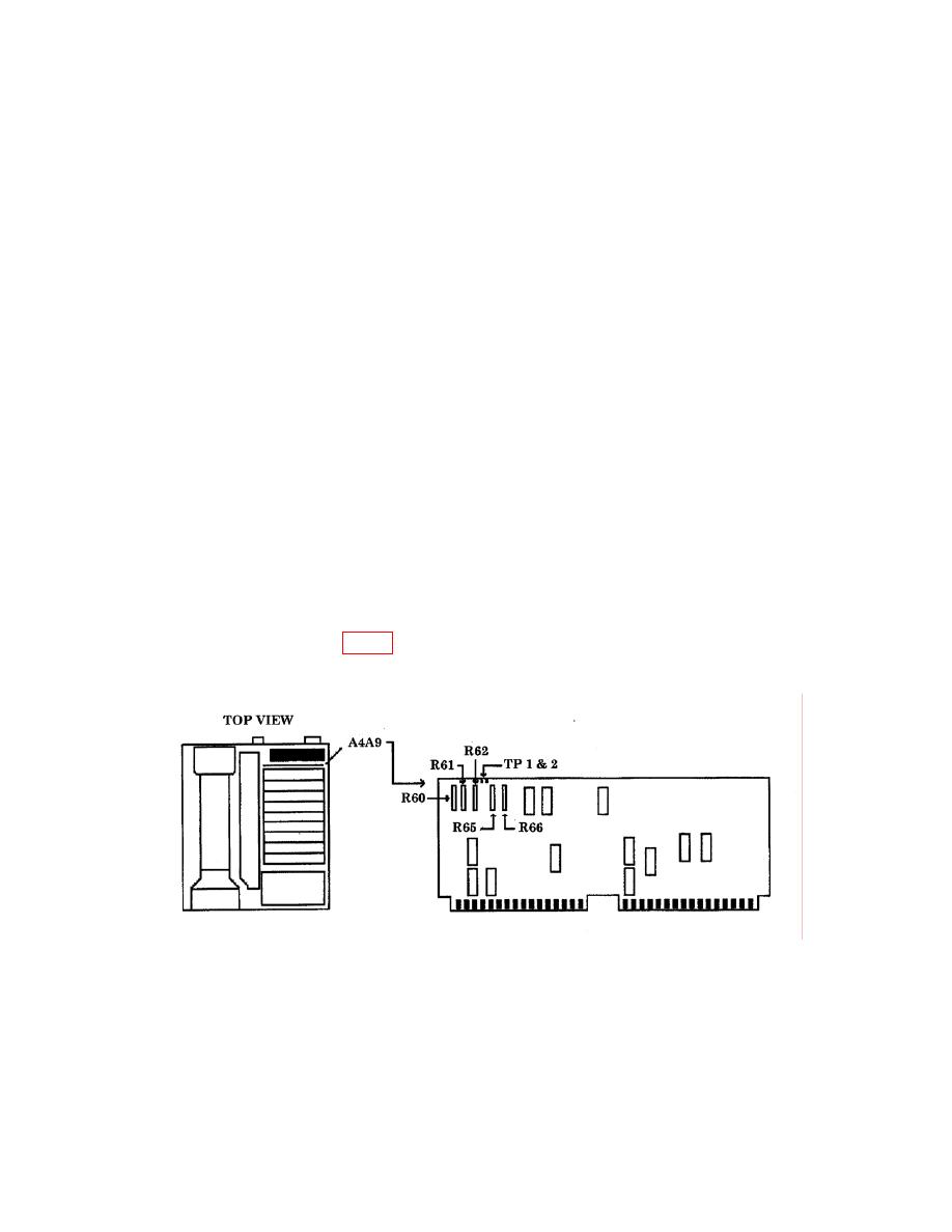
(6) Adjust A4A9R60 (fig. 8) for a MKR ∆ indication of 1.5 MHz while maintaining
marker at the -3 dB point using TI DATA knob (R).
Figure 8. A4A9 board.
(7) Press TI MARKER ∆ key.
(8) Adjust TI DATA knob to set marker to the -3dB point on the negative going
side of the displayed signal. There are now two markers; one on each side of the signal at
the -3 dB points.
20


