
TB 9-6625-2343-40
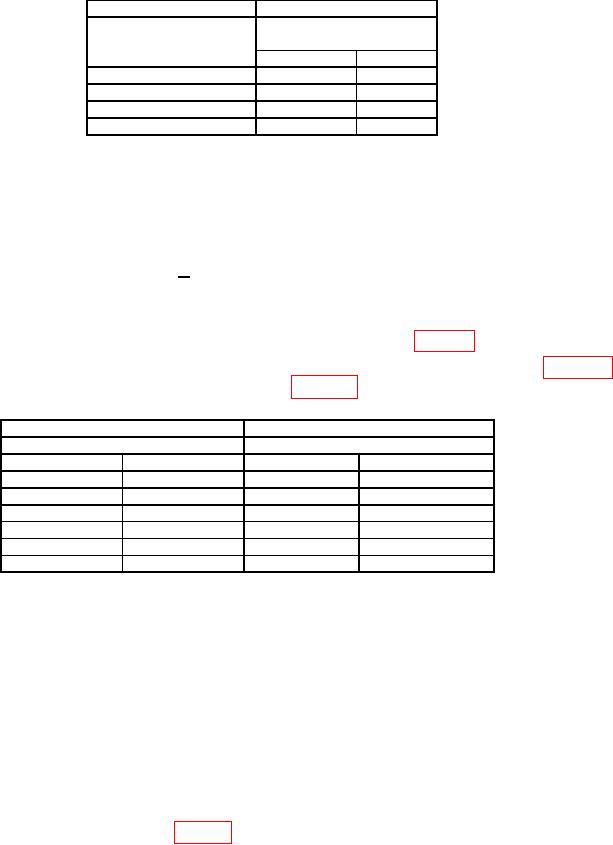
Table 15. Distortion Accuracy, 800 Hz to 2 kHz
Calibrator
Test instrument
Indications
Output
(%)
Min
Max
800
Hz
0.89
1.12
1200
Hz
0.89
1.12
1600
Hz
0.89
1.12
2
kHz
0.89
1.12
(41) Reduce all outputs to minimum and disconnect calibrator and audio analyzer
from TI.
(42) Connect function/arbitrary generator OUTPUT to TI MODULATION
OUTPUT/AUDIO INPUT using a 50 Ω feed through termination.
(43) Press TI keys as listed in (a) and (b) below:
(a) MEASUREMENT S (shift).
(b) AUDIO FREQ.
(44) Set function/arbitrary generator for a sine wave output of 20 Hz at a level of 3 V.
(45) If TI does not indicate within limits specified in first row of table 16, perform b below.
(46) Repeat technique of (44) above for remaining frequencies and levels in table 16.
If TI indications are not within limits specified in table 16, perform b below.
Table 16. Audio Counter Accuracy
Function/arbitrary generator
Test instrument
Output
Indications (Hz)
Level
Min
Max
20 Hz
3.0 V
19.98
20.02
20 Hz
100
mV
19.98
20.02
1 kHz
100
mV
999.97
1000.03
1 kHz
3.0 V
999.97
1000.03
250 kHz
3.0 V
249997
250003
250 kHz
100
mV
249997
250003
(47) Reduce all outputs to minimum and disconnect equipment setup.
b. Adjustments
(1) Reduce all outputs to minimum and disconnect equipment setup.
(2) Press TI INSTR PRESET.
(3) Remove any cable from TI MODULATION OUTPUT/AUDIO INPUT.
(4) Press TI keys as listed in (a) through (d) below:
(a)
DATA 30.0.
(b)
DATA SPCL.
(c)
DATA 49.7.
(d)
DATA SPCL.
(5) Adjust A52R47 RMS OFS (fig. 15) for a TI indication of between -0.0005 and 0.0005. (R)
31