
TB 9-6625-2343-40
(2) Connect TI CALIBRATION RF POWER OUTPUT to TI sensor module.
(3) Press TI keys as listed in (a) through (e) below:
(a)
BLUE.
(b)
INSTR PRESET.
(c)
DATA 45.16.
(d)
DATA SPCL.
(e)
TRACK MODE.
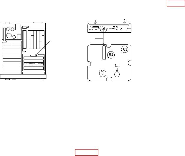
(4) If TI frequency indication is not between 49.5 and 50.5 MHz remove the thumb
screw retaining the A32 oscillator and slide the assembly out. Adjust A32L1 (fig. 17)
for 50 MHz 0.5 MHz.
R4 LEVEL
A32
ADJ
POWER REFERENCE
ADJUST
Figure 17. A32 board.
(5) Reinstall A32 assembly.
NOTE
The TEGAM IIA measuring system must be warmed up for at
least 2 hours and connected in standard configuration prior to
taking measurements.
(6) Connect equipment as shown in figure 16.
(7) Press multimeter keys as listed in (a) through (e) below:
(a)
Blue shift, RESET.
(b)
DCV.
(c)
Blue shift, AUTO.
(d)
Blue shift, N, 8, ENTER.
(e)
N RDGS/TRIG, 1, ENTER.
(8) Press TI keys as listed in (a) and (b) below:
(a) DATA 45.16.
(b) DATA SPCL.
34