
TB 9-6625-2343-40
(g) DATA SPCL.
(9) Set range calibrator to 10 W range.
(10) If TI does not indicate within limits specified in first row of table 18, perform b below.
(11) Repeat technique of (8) (f), (g) and (9) above for remaining range calibrator
ranges and TI special functions in table 18. If TI indication is not within limits specified in
table 18, perform b below.
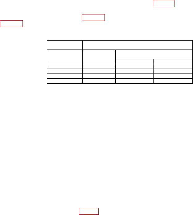
Table 18. Range to Range Accuracy
Range
Test
calibrator
instrument
Special
Range
function
Indications
Min
Max
10 W
10.1
9.90 W
10.10 W
100 W
10.2
99.4
W
100.6 W
10 mW
10.4
9.94 mW
10.06 mW
100 mW
10.5
99.0
mW
101.0 mW
(12) Set range calibrator to 1 mW range.
(13) Press TI keys as listed in (a) and (b) below:
(a) DATA 10.3.
(b) DATA SPCL.
(14) Set range calibrator to 100 W range.
(15) If TI does not indicate between 0.099 mW and 0.101 mW, perform b below.
(16) Press TI keys as listed in (a) and (b) below:
(a) BLUE.
(b) INSTR PRESET.
(17) Reduce all outputs to minimum and disconnect equipment setup.
b. Adjustments
(1) Reduce all outputs to minimum and disconnect equipment setup.
(2) Connect range calibrator POWER METER connector to TI SENSOR input.
(3) Set range calibrator to calibrate 1 mW range and normal polarity.
(4) Press TI RF POWER key.
(5) Adjust A53R40 FREQ (fig. 18) for a maximum indication on TI display.
36