
TB 9-6625-2343-40
TP4
R13 RMG 4
R40 FREQ
R16 RNG 5
A53
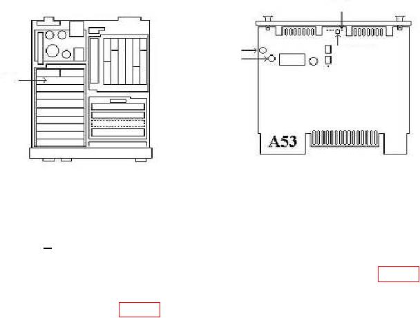
Figure 18. A53 board.
(6) Press TI keys as listed in (a) and (b) below:
(a) S.
(b) AUDIO FREQ.
(7) Connect TI MODULATION OUTPUT/AUDIO INPUT to A53TP4 (fig. 18).
(8) TI indication should be between 204 and 236 Hz.
(9) Disconnect A53TP4 (fig. 18) from TI MODULATION OUTPUT/AUDIO INPUT.
(10) Set range calibrator to standby.
(11) Press TI keys as listed in (a) and (b) below:
(a) RF POWER.
(b) ZERO. (Wait for the instrument to zero.)
(12) Set range calibrator to calibrate.
(13) Press TI keys as listed in (a) through (e) below:
(a)
CALIBRATION CALIBRATE.
(b)
BLUE.
(c)
CALIBRATION CALIBRATE.
(d)
DATA 10.4.
(e)
DATA SPCL.
(14) Set range calibrator to 10 mW range.
(15) Turn TI off, remove covers and extend A53 board.
(16) Connect extender cable to RF power assembly and connect range calibrator to
sensor connector on extender cable.
(17) Set range calibrator to standby.
(18) Press TI ZERO key.
37