
TB 9-6625-2346-35
(6) Adjust R309 (fig. 1) for digital multimeter indication recorded in (4) above.
(7) Set TI A TRIGGER A&B INT switch to CH 2.
(8) Repeat (4) through (7) above until digital multimeter indications in (4) and (6)
are within 1 mV dc.
(9) Disconnect digital multimeter.
(10) Position TI switches as listed in (a) through (e) below:
(a) VERTICAL MODE CH 1 BOTH CH2 to CH 1.
(b) CH 1 VOLTS/DIV to .1.
(c) CH 1 and CH 2 AC GND DC to AC.
(d) A AND B SEC/DIV to 10 s.
(e) A TRIGGER A&B INT to CH 1.
(11) Connect oscilloscope calibrator SOURCE/MEASURE CHAN 1 to TI CH 1
using 50Ω feed through termination.
(12) Set oscilloscope calibrator for a SOURCE/MEASURE CHAN 1, LEVEL SINE
output of 50 kHz and 2.2 divisions of vertical display on TI.
(13) Set TI CH 1 VOLTS/DIV switch to 1.
LEVEL control slowly so that A TRIGGER is just able to be maintained (R).
(15) Set TI CH 1 VOLTS/DIV switch to 50m and adjust A TRIGGER LEVEL
control fully cw.
(16) Set oscilloscope calibrator LEVEL SINE output amplitude for 5 divisions of
vertical display on TI.
(17) Set TI CH 1 VOLTS/DIV switch to .5.
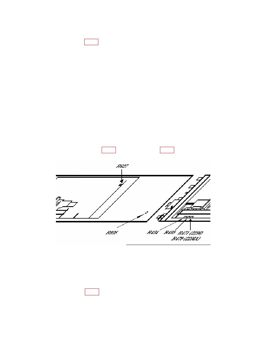
(18) Adjust R434 (fig. 2) so display just solidly triggers on positive peak of signal (R).
28
