
TB 9-6685-316-50
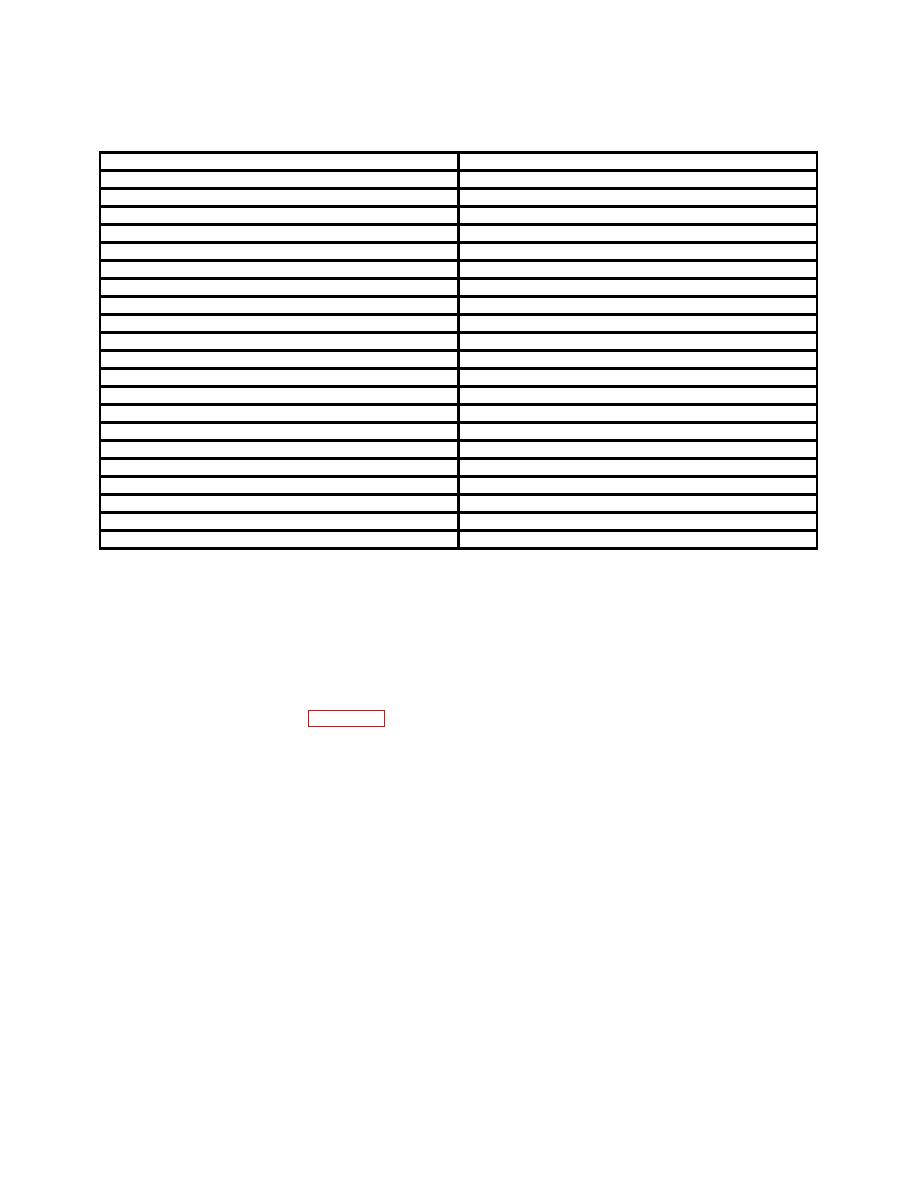
Nominal pressure
Tolerance2
0-160 psi gage
0.4
50
0.5
100
0.4
150
0-600 psi gage
1.5
100
1.5
200
1.5
300
1.5
400
1.5
500
0-5000 psi gage3
12.5
1000
12.5
2000
12.5
3000
12.5
4000
0-10,000 psi gage
25
1000
25
3000
25
5000
25
7000
25
9000
1Refer
to Report of Calibration for weight combination.
2Allowable deviation from value specified on Report of Calibration for weight combination indicated.
3Install high-range piston.
CAUTION
Do not remove gage or weights until pressure has been
released from system, and do not exceed pressure range of
gage
(1) Deviations either plus or minus by a constant value are corrected by
repositioning the pointer. Remove the bezel ring, loosen the locking screw (marked L)
1/4 turn, and adjust the screw marked "A." Tighten the locking screw and install the
bezel ring.
(2) Deviations varying linearly over the range of the TI are corrected by
repositioning the link screw. Remove the protective back or case from the mechanism,
loosen the link screw and move in the slot of the sector as required. Tighten the link
screw and install the protective back or case.
12
