
TB 9-5895-1913-40
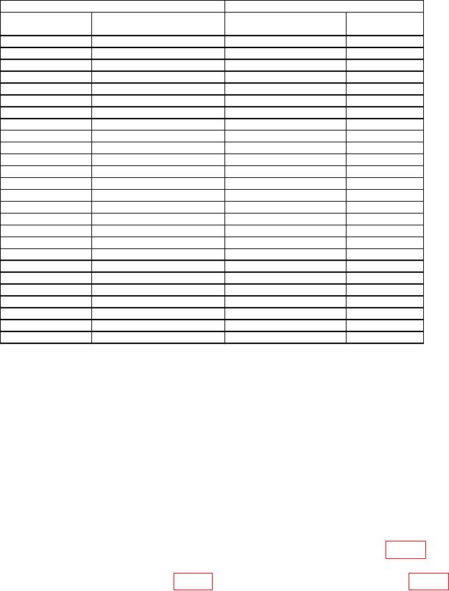
Table 4. Harmonics Verification Continued.
TI
Measuring receiver
Output Level
Fundamental frequency
Harmonic frequency
Tolerance
(dbm)
(MHz)
(MHz)
(dBc)
≤ -60
+24
44
88
≤ -60
+24
44
132
≤ -60
+24
62.5
125
≤ -60
+24
62.5
187.5
≤ -60
+24
88
176
≤ -60
+24
88
264
≤ -60
+24
125
250
≤ -60
+24
125
375
≤ -60
+20
250
500
≤ -60
+20
250
750
≤ -60
+20
354
708
≤ -60
+20
354
1062
≤ -60
+20
500
1000
≤ -60
+20
500
1500
≤ -60
+20
714
1428
≤ -60
+20
714
2142
≤ -60
+20
1000
2000
≤ -60
+20
1000
3000
≤ -55
+20
1400
2800
≤ -55
+20
1400
4200
≤ -55
+14
1800
3600
≤ -55
+14
1800
5400
≤ -55
+14
2700
5400
≤ -55
+14
2700
8100
≤ -55
+14
4000
8000
≤ -55
+14
4000
12000
(6) Set the TI controls as listed in (a) through (d) below:
(a) MODE to Leveled Sine.
(b) FREQUENCY to 2.1 GHz.
(c) LEVEL to +4.6 dBm.
(d) OUTPUT to OPER.
(7) Adjust measuring receiver as necessary to measure the amplitude of any
spurious signals at offsets > 3 kHz from the output frequency within the range of 1 MHz.
Example: With a fundamental frequency of 2.5 GHz, measure level of spurs between
2.500003 GHz and 2.501000 GHz satisfying the >3 kHz to +1 MHz requirement and
measure again between 2.499997 GHz and 2.499000 GHz, satisfying the < 3 kHz to
-1 MHz requirement.
(8) Verify that the measuring receiver indication is within the limits of table 5.
(9) Repeat technique of (6) (b), (7) and (8) above for the remaining fundamental
9

