
TB 9-6625-1999-35
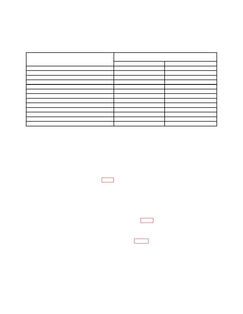
Measuring receiver indication
Attenuator switch setting
(dB)
Min
Max
+10
9
11
0
-1
1
-10
-11
-9
-20
-21
-19
-30
-31
-29
-40
-41
-39
-50
-51
-49
-60
-61
-59
-70
-71
-69
-80
-81
-79
-90
-91
-89
-100
-101
-99
-110
-111
-109
b. Adjustments
(1) Repeat a (3) above and determine average of maximum and minimum output
voltage indications on true rms voltmeter. Record average value.
(2) Set RANGE switch and adjust FREQUENCY controls to a frequency that gives
an output voltage indication equaling value recorded in (1) above on true rms voltmeter.
(3) Adjust ATTENUATOR VERNIER control for a 0.9 V indication on true
rms voltmeter.
(5) Repeat a above.
16. Power Supply
a. Performance Check
(1) Set POWER switch to off.
(3) Set POWER switch to ON and allow 10 minutes for warm-up and stabilization.
If multimeter does not indicate between -192 and -208 V dc, perform b below.
on multimeter (R).
17. Final Procedure
a. Deenergize and disconnect all equipment.
b. Annotate and affix DA label/form in accordance with TB 750-25.

