
TB 9-6625-1999-35
b. Adjustments
(1) Connect multimeter between output tap of audio transformer A1T1 (fig. 1)
(yellow lead on tie point) and chassis ground.
(3) Repeat a above.
22. RF Output Accuracy
a. Performance Check
(1) Connect measuring receiver to RF OUT 50 Ω.
(2) Position controls as listed in (a) through (c) below:
(a) MODULATION SELECTOR switch to CW.
(b) RANGE switch to 19MC-65MC.
(c) FREQUENCY dial to 65MC.
(2) Adjust ATTENUATOR VERNIER control while observing R.M.S. VOLTS
meter. Meter pointer will sweep full range of meter.
(3) Set ATTENUATOR switch to +20 DBM.
(4) Adjust ATTENUATOR VERNIER control for a 0 DBM indication on R.M.S.
VOLTS meter. Measuring receiver will indicate between 19 and 21 dB.
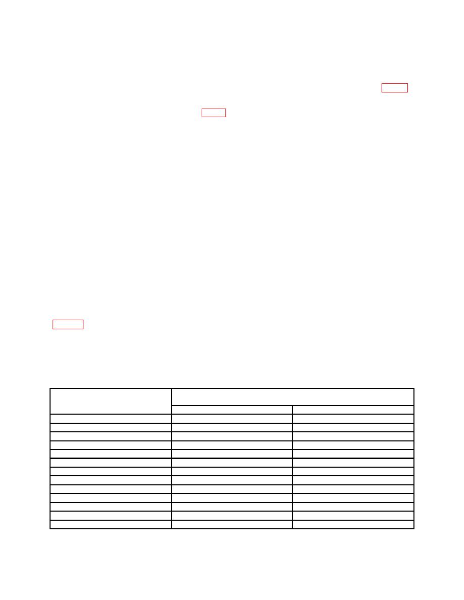
(5) Repeat technique of step (5) above for ATTENUATOR switch settings in
NOTE
If necessary, adjust ATTENUATOR VERNIER control to
maintain a 0 (zero) DBM indication on R.M.S. VOLTS meter
during remainder of check.
Measuring receiver indication
Attenuator switch setting
(dB)
Min
Max
+10
9
11
0
-1
1
-10
-11
-9
-20
-21
-19
-30
-31
-29
-40
-41
-39
-50
-51
-49
-60
-61
-59
-70
-71
-69
-80
-81
-79
-90
-91
-89
-100
-101
-99
-110
-111
-109

