
TB 9-6625-1999-35
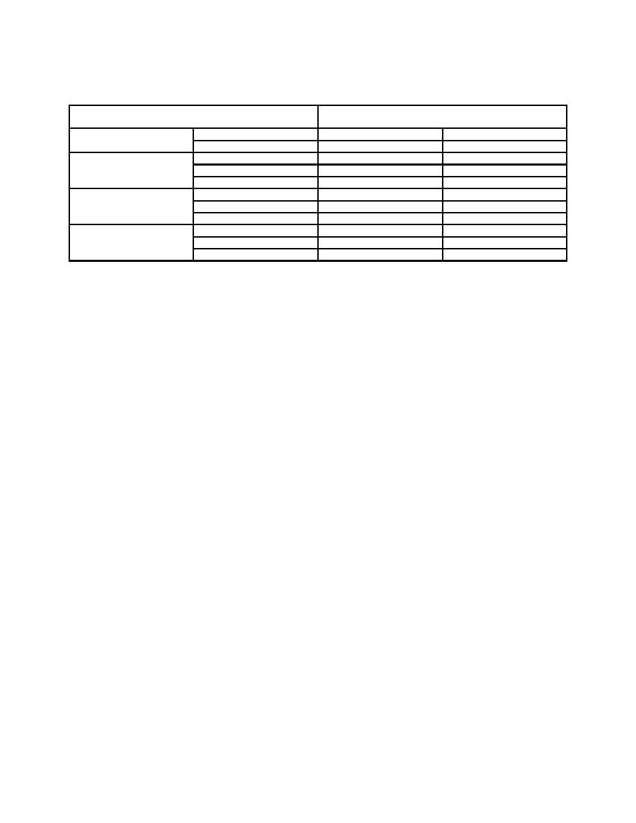
Table 6. Frequency Accuracy Continued
Frequency counter indications
Test Instrument
(MHz)
530KC - 180KC
900
0.891
0.909
Continued
1800
1.782
1.818
1.76MC-6.0MC
1.76
1.7424
1.7776
3.0
2.97
3.03
6.0
5.94
6.06
5.8MC - 19.2MC
5.8
5.742
5.858
9.0
8.91
9.09
19.2
19.008
19.392
19MC - 65MC
19
18.81
19.19
40
39.6
40.4
65
64.35
65.65
b. Adjustments. No adjustments can be made.
24. Carrier Zero Set
a. Performance Check
CAUTION
Throughout procedure, adjust ATTENUATOR VERNIER
control fully ccw before changing RANGE switch setting.
(1) Position controls as listed in (a) through (f) below:
(a) RANGE switch to 50KC-170KC.
(b) ATTENUATOR VERNIER control fully ccw.
(c) ATTENUATOR switch to 1.0 VOLTS.
(d) MODULATION SELECTOR switch to EXT. DC.
(e) MODULATION AMPLITUDE control fully ccw.
(f) FREQUENCY control to low end of band.
(2) Connect oscilloscope vertical input to RF OUTPUT 50Ω, using termination.
(3) Adjust oscilloscope vertical gain for calibrated 50 mV per division and horizontal
for a free-running condition so that indication will not disappear for lack of sync signal.
oscilloscope waveform peak-to-peak amplitude is not less than 80 mV over entire range,
perform b below.
(5) Repeat (4) above for remaining RANGE switch settings up to 10 MHz.
b. Adjustments
(1) Adjust output frequency control to frequency where amplitude is 80 mV
or greater.

