
TB 11-6625-2713-50
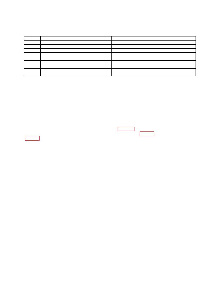
Table 3. Accessories Required
Item
Common name and/or official nomenclature
Description and part number
B1
Adapter (Adapter, Connector)
UHF jack To BNC plug (10054847)
B2
Adapter (Adapter, Connector)
UHF plug To BNC jack (10519439)
B3
Adapter
BNC T type, 2 jacks, 1 plug (MS35173-274C)
B4
Cable (Cable Assembly, RF Frequency
30 inch RG-58/U; BNC plug to BNC plug
terminations (7907467)
B5
Cable (Lead, Test)
36 inch RG-58/U; BNC plug to double banana
plug terminations (7907471)
B6
Standardizer
5 to 47 picofarad, UHF plug to UHF jack (SKD
4850-44).
SECTION III
PRELIMINARY OPERATIONS
6. Preliminary Instructions
Personnel should become familiar with the entire bulletin before beginning the calibration.
b. Items of equipment used in this procedure are referenced within the text by common
name and item identification number as listed in tables 2 and 3. For the identification of
equipment referenced by item numbers prefixed with A, see table 2, and for prefix B, see
WARNING
HIGH VOLTAGE is used during the performance of this
calibration. DEATH ON CONTACT may result if personnel
fail to observe safety precautions.
7. Equipment Setup
a. Position TI controls as listed in (1) through (9) below:
(1) Set MAIN TRIG switches as follows:
(a) SOURCE switch to INT.
(b) COUPLING switch to AC.
(c) SLOPE switch to + (positive).
(2) AUTO-TRIG-SINGLE switch to AUTO.
(3) Horizontal mode switch to EXT HOR.
(4) TIME/DIV switch to 1 MSEC and VARIABLE control to CAL.
5
