
TB 9-4920-469-24
(50)Set the RANGE switch to 20MΩ.
(51)Connect the TI clips to Resistance Standard NO.2, set to 20.00 MΩ, and press
the PTM pushbutton.
(52)The TI displays the measured value prior to compensation being applied.
(53)Set the RANGE switch to 200MΩ.
(54)Connect the TI clips to Resistance Standard NO.2, set to 199.3 MΩ, and press
the PTM pushbutton.
(55)The TI displays the measured value prior to compensation being applied.
(56)Disconnect clips from Resistance Standard. Short the TI clips together.
(57)Set the FUNCTION switch to TEMP MEAS.
(58)The TI displays the mV offset adjust value.
(59)Connect TI to Calibrator Binding Posts observing polarity.
(60)Set calibrator to 0.000 mV dc and press OPR.
(61)The TI displays the calculated mV offset value.
(62)Set calibrator to 55.000 mV dc and press OPR.
(63)The TI displays the calculated full-scale value.
(64)The TI will now do the mV amb Offset calculation.
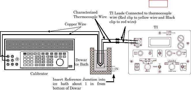
(65)Disconnect TI from calibrator and connect as illustrated in figure 2.
Figure 2. Equipment Setup (Model TT1200A).
(66)Set calibrator to 0.000 mV dc and press OPR.
(67)Press TI C (ENT) key.
(68)The TI does a 10-minute countdown to zero (0) minutes; then displays the
calculated mV amb Offset value.
(69)Disconnect equipment.
(70)Set the FUNCTION switch to RES MEAS.
16