
TB 9-4931-501-35
(4) Adjust calibration fixture POSITION control to align bright center trace of
display with TI center horizontal graticule line.
(5) If center seven traces do not coincide within 0.1 division of respective
horizontal graticule lines, perform b below.
(6) Press TI POWER switch to off and remove calibration fixture from left and
install in TI center compartment.
(7) Pull TI POWER switch to on and repeat (4) and (5) above and if necessary,
repeat b below for optimum gain setting compromise for both vertical compartments.
center seven horizontal graticule lines (R).
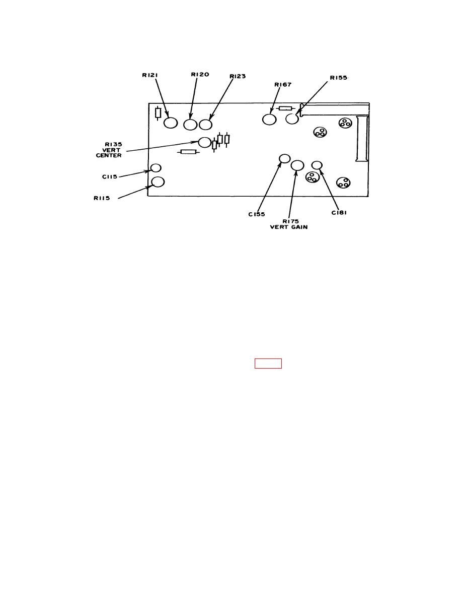
15. Vertical Compensation
a. Performance Check
(1) Press TI POWER switch to off. Remove calibration fixture (A2) from center
and install in TI left compartment. Pull TI POWER switch to on.
(2) Set calibration fixture TEST switch to VERT OR HORIZ + STEP RESP and
REP RATE switch to 100 kHz. Adjust AMPLITUDE and POSITION controls for a 6-
division display centered vertically on TI graticule.
