
TB 9-6625-102-24
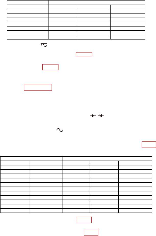
Table 3. mV DC Voltage And Linearity.
TI
Calibrator
Range (V dc)
Voltage (V dc)
Min (V dc)
Max (V dc)
50 m1
50 m
49.925
50.075
500 m
500 m
499.83
500.18
1
1000 m
999.3
1000.8
52
5
4.9983
5.0018
50
50
49.983
50.018
500
500
499.80
500.20
1000
1000
999.2
1000.8
Short test leads and Null the TI before making measurement.
1
Set rotary switch to
V.
2
(4) TI will indicate within the limits of table 3; if not, perform b below.
(5) Repeat technique of (2)(c) through (4) above for remaining TI ranges and
calibrator output voltages in table 3.
(6) Set calibrator output to minimum.
b. Adjustments. Perform entire calibration procedure before performing alignment
procedure listed in paragraph 17.
9. AC Voltage Accuracy
a. Performance Check
ΩTEMPVmV and COM inputs.
(1) Connect calibrator OUTPUT HI and LO to TI
(2) Set the TI as listed in (a) and (b) below:
(a) Set rotary switch to
V.
(b) Press the RANGE key to the 5 V range.
(3) Set the calibrator voltage and frequency output to the first values in table 4.
Table 4. AC Voltage Primary Function.
Calibrator
TI
Voltage (VRMS)
Frequency (kHz)
Range (VRMS)
Min (VRMS)
Max (VRMS)
5
1
5
4.9775
5.0225
5
10
5
4.9775
5.0225
5
20
5
4.9585
5.0415
5
100
5
4.8130
5.1870
50
1
50
49.780
50.230
50
10
50
49.780
50.230
50
20
50
49.590
50.420
50
100
50
48.130
51.870
500
1
500
497.75
502.25
500
10
500
497.75
502.25
1000
1
1000
992.0
1008.0
(4) TI will indicate within the limits of table 4; if not, perform b below.
(5) Repeat technique of (2)(b) through (4) above for remaining TI ranges and
calibrator output voltage and frequency values in table 4.
(6) Reduce calibrator output to minimum.