
TB 9-6625-114-24
NOTE
TI uses the same input circuitry for the SCOPE and METER
modes. The remaining CHANNEL A deflection coefficients
will be checked when the METER mode is verified.
(7) Set calibrator to STBY and switch connection from TI CHANNEL A to TI
CHANNEL B.
(8) Press TI upper select/adjust keys to go to first test number listed in Step #
column of table 3.
(9) Set calibrator output to first value in Applied column of table 3.
(10) Adjust calibrator output to obtain corresponding number of divisions displayed
on TI as listed in Deflection column of table 3. If calibrator displayed output is not within
limits specified in Limits column of table 3, perform b below.
(11) Repeat technique of (8) through (10) above for values listed in table 3. If
calibrator displayed output is not within limits specified in Limits column of table 3,
perform b below.
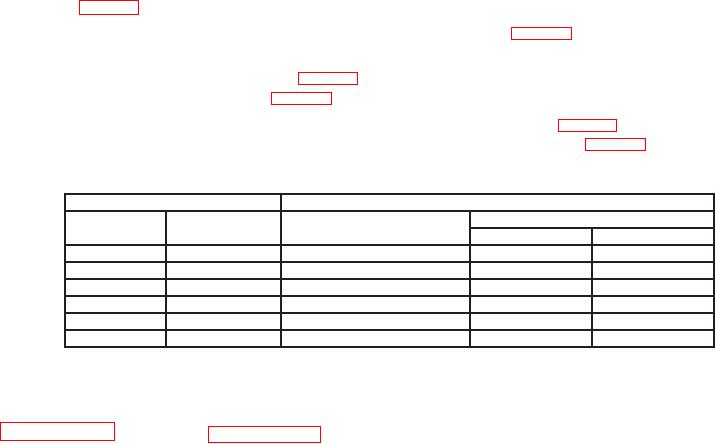
Table 3. Vertical deflection
Test instrument
Calibrator
Limits
Deflection
Step #
Applied
(div)
Min
Max
Verif 5
3
300
mV dc
294
mV
306
mV
Verif 5
6
212.13 mV @ 1 kHz
207.92 mV
216.34 mV
Verif 6
6
2.1213 V @ 1 kHz
2.0792 V
2.1634 V
Verif 6
3
3
V dc
2.94 V
3.06 V
Verif 7
3
30
V dc
29.4
V
30.6
V
Verif 7
6
21.213 V @ 1 kHz
20.792 V
21.634 V
(12) Set calibrator output to minimum and disconnect equipment setup.
b. Adjustments. Annotate out of tolerance condition. Complete checks through
9. Frequency Response
a. Performance Check
(1) Press TI upper select/adjust key to go to test 10 (skip tests 8 and 9). TI will
display Verif 10.
(2) Connect oscilloscope calibrator SOURCE/MEASURE CHAN 1 to TI CHANNEL
A and SOURCE/MEASURE CHAN 2 to TI CHANNEL B.
(3) Set oscilloscope calibrator for a channel 1, 50 kHz, LEVEL SINE output. Adjust
oscilloscope calibrator output amplitude for a 6 division display on TI screen.
(4) Without changing oscilloscope output amplitude, switch TI to test 11 using
upper select/adjust key. TI will display Verif 11.
(5) Increase oscilloscope calibrator output frequency to 50 MHz. If TI vertical
displayed amplitude is not •4.2 divisions, perform b below.