
TB 9-6625-114-24
(4) Adjust function generator output amplitude for 8 divisions (800 mV p-p) of trace
height on TI screen. If a line with an angle of 45 degrees and a gap of ”10 pixels is not
displayed, perform b below.
(5) Set function generator output to off and disconnect equipment setup.
b. Adjustments. Annotate out of tolerance condition. Complete checks through
14. Base Line Instability
a. Performance Check
(1) Use TI select/adjust keys to switch from front setting number 21 to number 22
and back to 21.
(2) If TI trace jumps more than 0.2 divisions while switching between front settings
21 and 22, perform b below.
b. Adjustments. Annotate out of tolerance condition. Complete checks through
15. Meter Voltage
a. Performance Check
(1) While in TI SERVICE menu, press METER soft-key. TI will display Verif 1.
NOTE
TI uses the same input circuitry for SCOPE and METER
modes. When the voltage accuracy of the METER is checked,
the deflection coefficients for SCOPE CHANNEL A are also
verified.
(2) Connect calibrator OUTPUT HI and LO to TI CHANNEL A input.
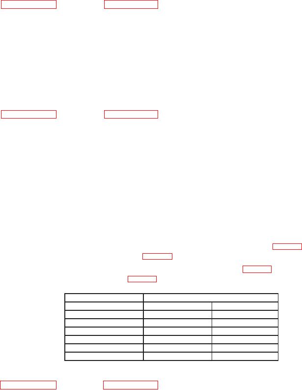
(3) Set calibrator output to first value listed in Output column of table 4. If TI does
not indicate within limits specified in table 4, perform b below.
(4) Repeat technique of (3) above for remaining values in table 4. If TI does not
indicate within limits specified in table 4, perform b below.
Table 4. Meter Voltage
Calibrator
Test instrument limits
Output
Min
Max
300 mV dc
298.0 mV dc
302.0 mV dc
3 V dc
2.980 V dc
3.020 V dc
30 V dc
29.80 V dc
30.20 V dc
300 mV @ 1 kHz
292.5 mV ac
307.5 mV ac
3 V @ 1 kHz
2.925 V ac
3.075 V ac
30 V @ 1 kHz
29.25 V ac
30.75 V ac
b. Adjustments. Annotate out of tolerance condition. Complete checks through