
TB 9-6625-127-24
am. Set TI FRQ to 1.00 MHz and adjust A1C204 (fig. 1) for a frequency counter
indication of 1.00 MHz 0.05 MHz. (R)
an. Repeat steps al and am above until both specifications are achieved.
ao. Set TI FRQ to 2.99 MHz and connect TI OUTPUT to oscilloscope 1 input. Connect
TI TRIG OUTPUT to oscilloscope 2 input.
ap. Set oscilloscope sweep to 100 ns / div and vertical deflection for a convenient
displayed amplitude.
aq. Record amplitude of displayed signal.
ar. Set TI FRQ to 9.99 MHz and check that output amplitude decreased by 2% to 4%
from amplitude recorded in step aq above.
as. Set TI FRQ to 10 MHz. Connect TI TRIG OUTPUT back to frequency counter A
input and adjust A2R17 (fig. 2) for a frequency counter indication of 10.00 MHz 0.03 MHz. (R)
at. Re-connect TI TRIG OUTPUT to oscilloscope 2 input.
au. Set TI FREQ to 2 MHz.
Use oscilloscope markers to mark current signal
amplitude.
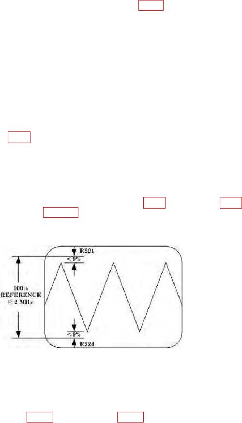
av. Set TI FREQ to 50 MHz.
symmetrical signal as shown in figure 3 below, and a measured frequency of 50.0 MHz
1.0 MHz. (Connect TI TRIG OUTPUT to frequency counter to measure frequency).
Figure 3. HF symmetry.
ax. Connect TI OUTPUT to spectrum analyzer input.
ay. Setup spectrum analyzer to display fundamental, at 0 dB, and at least first two
distortion. (R)
15