
TB 9-6625-127-24
(4) Repeat technique of (3) above for remaining OFS values listed in table 9. If
multimeter indication is not within limits specified in table 9, perform b below.
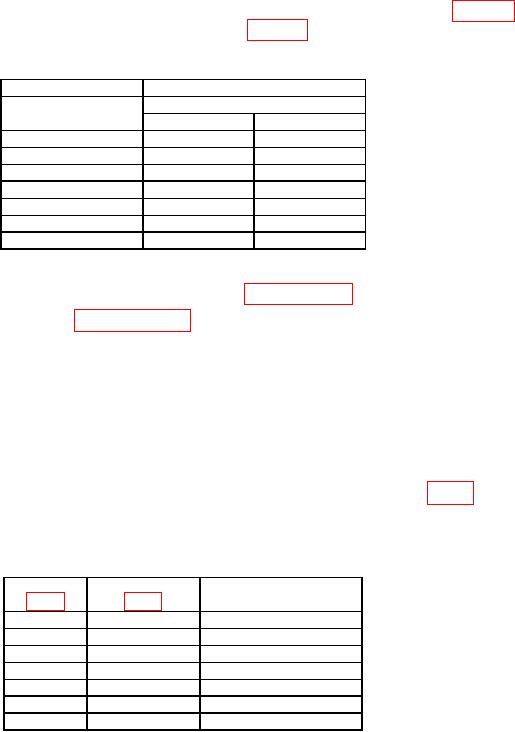
Table 9. DC Output
Test instrument
Multimeter indication
OFS
Limits (VDC)
(V)
Min
Max
7.95
7.890
8.010
5.00
4.955
5.045
2.00
1.970
2.030
0.00
-0.020
0.020
-2.00
-2.030
-1.970
-5.00
-5.045
-4.955
-7.95
-8.010
-7.890
(5) Set TI output to minimum and disconnect equipment setup.
(6) If no adjustments are required proceed to paragraph 17.
b. Adjustments. Perform paragraph 16.
16. Adjustment
NOTE
Adjustments must be performed in order.
a. Disconnect TI from power source and remove TI protective covers.
b. Connect TI to power source. Turn TI on and allow 1 hour warm-up.
c. Connect multimeter low terminal to TI ground test point on board A1 (fig. 1).
d. Test supply voltages and, if necessary, make adjustments to achieve result as shown
in table 10 below.
Table 9. DC Output
Test point
Adjustment
Result
A1+15 V
A1R24 (R)
+15.000 V 15 mV
A1-5.2 V
A1R12 (R)
-5.250 V 10 mV
A1+5.0 V
---------
+5.050 V 50 mV
A3+5.0 V
---------
+5.150 V 50 mV
A1+24 V
A1R18 (R)
+24.000 V 50 mV
A1-24 V
A1R19 (R)
-24.000 V 50 mV
A1-15 V
A1R25 (R)
-15.000 V 15 mV
e. Disconnect multimeter and set TI as outlined in (1) through (9) below:
MODE (Input) to NORM.
(1)
CTRL to off.
(2)
(3)
Waveform to square.
COMPL OUTPUT to off.
(4)
DISABLE OUTPUT to On.
(5)
FRQ to 100 kHz.
(6)