
TB 9-6625-151-40
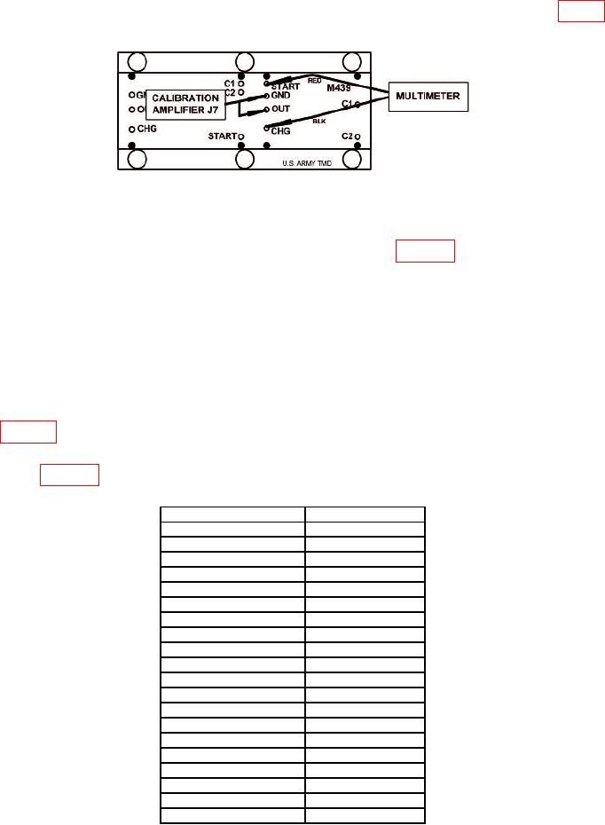
(2) Connect MULTIMETER HI and LO to TI M439 START and CHG (fig. 6).
CALIBRATION AMPLIFIER J7 should be connected to TI M439 OUT and GND.
Figure 6. M439 Rocket Motor Energy Test.
(3) Set MULTIMETER to measure resistance.
(4) Set TI SW1 Tube Select to first position listed in table 10.
(5) Depress and release S2 Timer Reset. Observe timer shows 0.000.
(6) Depress and release S8 Reset. Observe all Motor Energy LED's are Off.
(7) Set FUNCTION GENERATOR #1 and #2 outputs On.
(8) Depress and release FUNCTION GENERATOR #1 trigger switch.
Observe
corresponding TI Motor Energy LED should light.
(9) Observe Time Out LED remains lit for duration of TOF. Observe timer
indicates between 1.940 and 2.060 sec. MULTIMETER will indicate within limits listed
in table 10 for duration of TOF.
(10) Repeat technique of (4) through (9) above for remaining positions and limits
listed in table 10.
Table 10. Continuity J5-Ctr to J1-x.
Tube select
Multimeter
Max Ω
SW1
1
0.5
2
0.5
3
0.5
4
0.5
5
0.5
6
0.5
7
0.5
8
0.5
9
0.5
10
0.5
11
0.5
12
0.5
13
0.5
14
0.5
15
0.5
16
0.5
17
0.5
18
0.5
19
0.5
(11) Set FUNCTION GENERATOR #1 and #2 outputs Off.
14