
TB 9-6625-166-24
(4) Rotate calibrator knob below EDIT FIELD pushbutton to adjust calibrator
display indication to equal TI indication. Calibrator Err display will indicate within limits
specified for appropriate model in first row of table 6. If TI does not indicate within limits
specified in table 6, perform b below.
(5) Repeat technique of (3) and (4) above, down to 20 M using calibrator outputs
and TI indications listed in table 6. Calibrator Err display will indicate within limits
specified for appropriate model in table 6. If TI does not indicate within limits specified in
table 6, perform b below.
(6) Set calibrator output to minimum and disconnect equipment setup.
(7) Connect TI to resistance standard. Set TI rotary selector switch to 200 M and
resistance standard to200 M . Ti will indicate within the limits in Table 6 for the 200 M
range. If TI does not indicate within limits specified in table 6, perform b below.
(8) Set TI rotary selector switch to 2000 M and resistance standard to 2000 M .
Ti will indicate within the limits in table 6 for the 2000 M range. If TI does not indicate
within limits specified in table 6, perform b below.
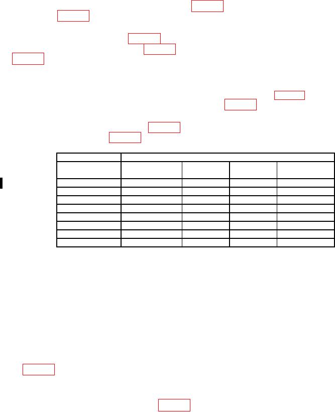
Table 6. Resistance Accuracy.
Test instrument
Calibrator
Min ( )
Max ( )
Err indication
Nominal output
Range ( )
( )
(%)
200
190
187.7
192.3
1.21
2
k
1.9
k
1.877
1.923 k
1.21
20
k
19
k
18.77
k
19.23 k
1.21
k1
200
k
190
187.7
k
192.3
k
1.21
2000
k
1.9
M
1877
k
1923
k
1.21
20
M
19
M
18.58 M
19.42 M
2.21
2
200
M
190
M
179.5 M
200.5 M
------
2000
M
1900
M
1795 M
2005
M
------
Calibrator 2-wire Comp: OFF.
1
Connect resistance standard to TI.
2
(9) Set calibrator output to minimum and disconnect equipment setup.
b. Adjustments. No adjustments can be made.
12. Capacitance Accuracy
a. Performance Check
(1) Connect capacitance standard output HIGH and LOW to TI F input terminal
and COM inputs and set all capacitance standard decades to zero.
(2) Set the TI rotary switch to 20 μF and the capacitance standard to the first value
in table 7.
(3) TI will indicate within the limits of table 7; if not, perform b below.
(4) Repeat technique of (2) and (3) above for remaining capacitance standard values
and TI range settings up to 200 μF in table 7.
(5) For the 2000 μF and 20 mF ranges repeat the technique of (2) and (3) above
except use the test reported values of the capacitance standard. The TI must read (4.0% of
rdg + 10 d) of the Test Report value.
(6) Set the capacitance standard to minimum and disconnect equipment setup.
Change 1