
TB 9-6625-172-24
c. Construct a 1-turn 14-gauge copper wire coil 6 inches in diameter.
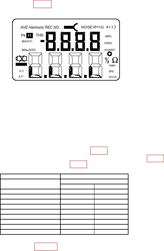
d. Press and hold FUNC key while turning on TI.
e. Compare TI display to figure 1 example below and check all display segments for
clarity and contrast.
Figure 1. Display.
f. Set TI function switch to OFF.
8. Resistance
a. Performance Check
(1) Connect 1-turn coil to resistance standard output terminals.
(2) Set TI function switch to Ω (TI displays CAL 7, 6, 5...Cal 1 and a beep is heard).
(3) Set resistance standard for 1 Ω and clamp TI around coil at output terminals. If
TI indication is not within limits specified in first row of table 3, perform b below.
(4) Repeat technique of (3) above for resistance standard values listed in table 3. If
TI indications are not within limits specified in table 3, perform b below.
Table 3. Resistance.
Resistance standard
Test instrument
Indication limits (Ω)
Output
(Ω)
Min
Max
1
0.935
1.065
9
8.765
9.235
12
11.52
12.48
90
88.15
91.85
110
105.7
114.3
200
193.0
207.0
400
375.0
425.0
600
530.0
670.0
1100
880.0
1320.0
(5) Disconnect equipment setup.
b. Adjustments. Perform section IV below.