
TB 9-6625-2059-24
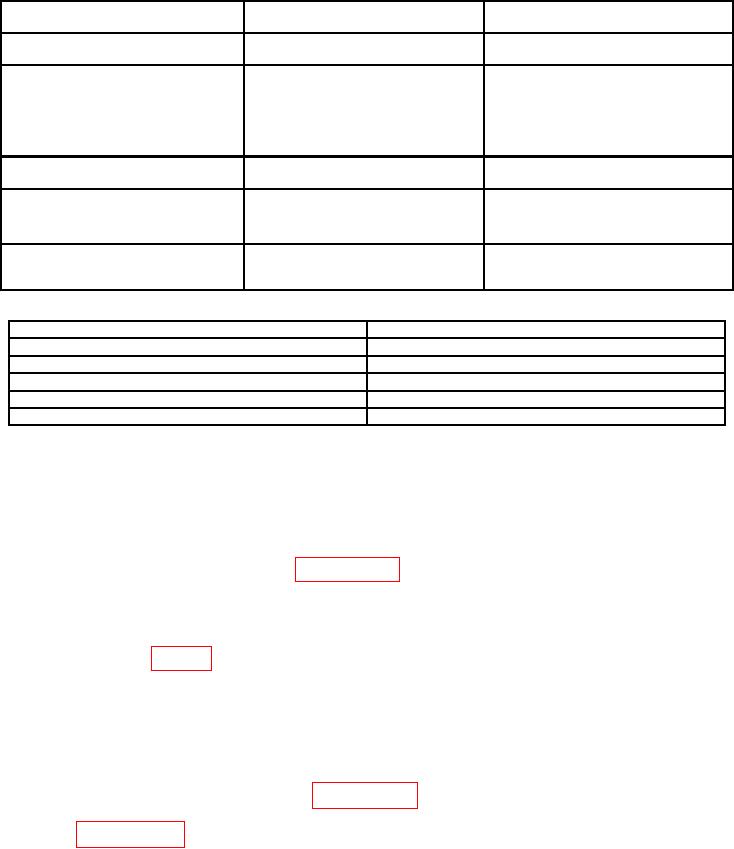
Table 2. Minimum Specifications of Equipment Required Continued.
Manufacturer and model
Common name
Minimum use specifications
(part number)
Range:
0.4 V p-p
Agilent, Model 54831M
Accuracy: 3%
(OS-303/G)
OSCILLOSCOPE CALIBRATOR
Range:
50 mV to 50 V p-p at 1
Fluke, Model 9500B/3200
kHz sine wave
(9500B/3200)
Accuracy: 1.25%
Range:
10 s to 1 ms markers
Accuracy: 0.5%
Range:
1 V p-p square wave
RESISTANCE STANDARD
Range:
28.5 to 315 kΩ
IET Labs, HARS-LX-9-0.001
Accuracy: 1.25%
(HARS-LX-9-0.001)
Bird, Model 4421 (4421) w/
RF POWER METER
Frequency: 450 kHz to 1000 MHz
Directional power sensors,
Output: 7.5 to 85 W
Model 4021 and 4022 (4021and 4022)
Accuracy: ( 3 %)
SIGNAL GENERATOR
Range:
100 kHz to 125 MHz
Aeroflex, Model 2023B (2023B
Amplitude: 0 to -107 dBm
OPT2/4/11/122)
Range:
60% MOD at 1 kHz
Table 3. Accessories Required.
Common name
Description (part number)
DC POWER SUPPLY
Kepco, Model HB525M (7915935)
DECADE RESISTOR
150 Ω Winslow, Model 336 (7907234)
LOW PASS FILTER
Telonic, Model TLC45-4EF
PROBE1
X1-X10 probe (supplied with multimeters MM-100E)
RF POWER AMPLIFIER
Ophir RF Inc, Model XRF733 (XRF733)
1 Do
not use probe AV-5388 supplied with some multimeters MM-100E.
CALIBRATION PROCESS
6. Preliminary Instructions
a. The instructions outlined in paragraphs 6 and 7 are preparatory to the calibration
process. Personnel should become familiar with the entire bulletin before beginning the
calibration.
b. Items of equipment used in this procedure are referenced within the text by common
name as listed in tables 2 and 3.
c. Unless otherwise specified verify the result of each test and, whenever the test
requirement is not met, take corrective action before continuing with the calibration.
Adjustments required to calibrate the TI are included in this procedure. Additional
maintenance information is contained in the manufacturers' manuals, TM 11-6625-3016-40-1,
and TM 11-6625-3016-20-1.
d. When indications specified in paragraphs 8 through 20 are not within tolerance,
perform the power supply check prior to making adjustments. After adjustments are made,
repeat paragraphs 8 through 20. Do not perform power supply check if all other
parameters are within tolerance.
e. Unless otherwise specified, all controls and control settings refer to the TI.
5