TB 9-6625-2071-35
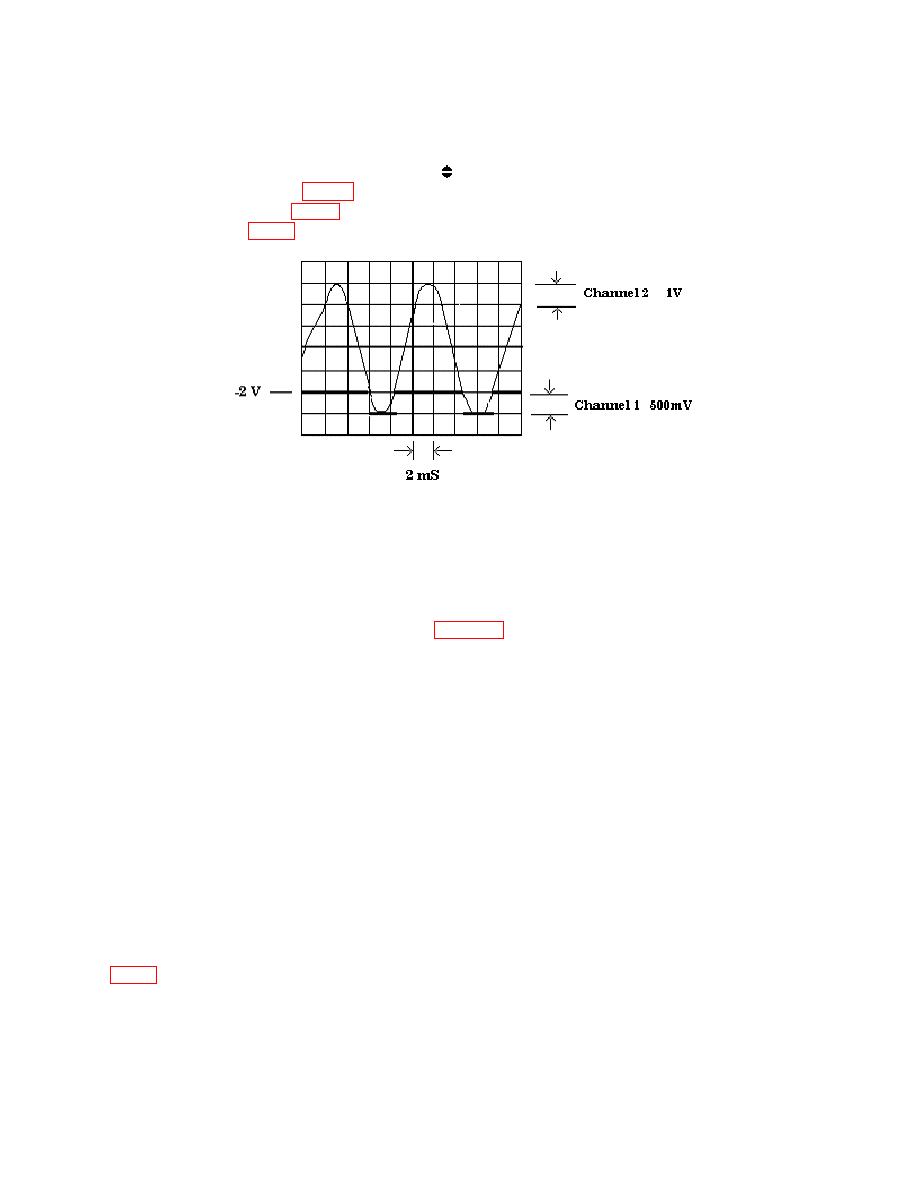
(14) Execute TI command string PF4G6S1S3A379-200*B37-200*R.
control so that the top of TI marker output
(15) Adjust oscilloscope Vertical 1
waveform on channel 1 (fig. 5) just barely intersects both positive and negative slopes of
sine wave on channel 2 (fig. 5). If this intersection does not occur at -2.00 V 35 mV on sine
wave, as shown in fig. 5, perform b below.
(16) Move oscilloscope Vertical 1 connection from TI CHANNEL A MARKER
OUTPUT to TI CHANNEL B MARKER OUTPUT.
(17) Repeat (15) above.
b. Adjustments
(1) Connect equipment as shown in figure 6.
(2) Set resistance standard to 0 Ω and multimeter to measure V dc, autorange.
(3) Set oscilloscope channel 2 off and channel 1 on. Set channel 1 for DC input
coupling, 1 MΩ input, 500mV/div amplitude and 5 s/div sweep.
(4) Set oscilloscope triggering for positive slope, auto level, channel 1 source
and DC coupling.
(5) Set function generator as listed in (a) through (e) below:
(a)
Function to sine wave.
(b)
Frequency to 20 kHz.
(c)
Amplitude to 70 mVp-p.
(d)
Offset to 0 V dc.
Function Outputs to 50 Ω.
(e)
(6) Execute TI command string PF4G6S1S3A379+000*B37+000*R.
(7) Adjust oscilloscope controls as necessary to view waveform. Adjust A11R21
14


