TB 9-6625-2083-24
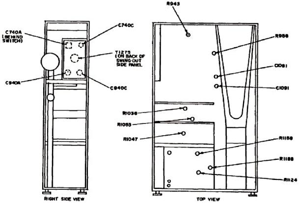
Figure 8. Top and right side view - adjustment locations.
25. Horizontal Gain
a. Performance Check
(1) Set HORIZ DISPLAY switch to A and VOLTS/DIV switches to .5.
(2) Set oscilloscope calibrator MARKER output for 1 ms and rotate oscilloscope
calibrator knob located below EDIT FIELD pushbutton to align 1 marker per division on
the middle 8 vertical divisions. If oscilloscope calibrator Err display readout does not
indicate within 3%, perform b (1) below.
(3) Adjust oscilloscope calibrator MARKER output for 0.1 ms.
(4) Set MAG switch to X10.
(5) Repeat technique of (2) above. If oscilloscope calibrator Err display readout does
not indicate within 3%, perform b (2) below.
(6) Adjust oscilloscope calibrator MARKER output for 5 ms.
(7) Adjust horizontal POSITION control to align middle marker (3 markers on total
sweep) on vertical graticule center line.
(8) Set MAG switch to OFF. If middle marker does not remain on center vertical
graticule line, perform b (3) below.

