TB 9-6625-2134-24
(8) Press CAL pushbutton to on and adjust FREQUENCY control for a 1.0 GHz
readout on crt.
(9) Press CAL pushbutton to off.
(10) Position FREQUENCY SPAN/DIV control for a readout of 200 MHz on crt and
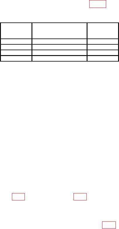
repeat technique of (3) through (7) above for each comb marker. Crt readout must equal
1.500 GHz (5 MHz +20 percent SPAN/DIV) X n (refer to table 3, for n) or (0.2 percent of
center frequency +20% SPAN/DIV), whichever is greater.
Table 3. Harmonic Number (n) Versus Frequency Range
FREQUENCY RANGE
n
Bands
pushbutton settings
(GHz)
1
0.0 - 1.8
1
2
1.7 - 5.5
1
3
3.0 - 7.1
1
4
5.4 - 18
3
(11) Repeat technique of (3) through (7) above for bands 1 through 3 in increments of
2 GHz with applied limit (0.2 percent of center frequency + 20 percent of SPAN/DIV)
above 2.5 GHz.
NOTE
To check the higher bands, it may be necessary to increase
REFERENCE LEVEL control to -10 dBm to locate true
response of 500 MHz comb. MIN RF ATTEN dB should not
be decreased below 10 dB unless TI has preselector. When
checking TI with preselector, adjust PEAKING control for
maximum signal response when operating above band 1 (0 to
1.8 GHz), as each signal is tuned to center screen.
b. Adjustments
NOTE
Perform (1) through (37) below only if power supply adjustment
was required or visual inspection of crt indicates that display is
not properly illuminated, focused, or aligned.
(1) Push POWER switch to off, and adjust INTENSITY control fully ccw.
(2) Set MANUAL SCAN control to midrange and set TIME/DIV switch to MNL.
(4) Pull POWER switch to on and after power stabilization, press VERTICAL
DISPLAY 2 dB/DIV pushbutton to on.
(5) Press READOUT pushbutton and DIGITAL STORAGE pushbuttons to off.
(6) Connect multimeter to collector of Q4058 or Q4059 (fig. 2) and ground, record
multimeter indication.
10

