
TB 9-6625-2134-24
(39) Set TIME/DIV switch to 5 ms.
(40) Press 2 dB/DIV VERTICAL DISPLAY pushbutton to on.
(41) Press DIGITAL STORAGE pushbuttons to off.
(42) Align trace on bottom graticule line, using vertical POSITION control.
(43) Adjust function generator for a 5 kHz sine wave at 4 V p-p (square wave can be used also).
NOTE
Adjust dc offset on function generator to view full display.
(44) Adjust R1066 (fig. 1) for a full screen.
(45) Disconnect signal source and jumper from TI.
(46) Connect multimeter to TP1061 (fig. 1) and ground.
(47) Set TIME/DIV switch to MNL and adjust MANUAL SCAN control for 0.0 V
indication on multimeter.
(48) Position dot on center vertical graticule line with horizontal POSITION control.
(49) Adjust MANUAL SCAN control for an indication of +5 V on multimeter.
(50) Adjust R1055 (fig. 1) to position dot on far right graticule line of crt.
(51) Adjust MANUAL SCAN control until dot is positioned on far left graticule line
on crt. If multimeter does not indicate approximately -5 V, repeat technique of (47) through
(50) above.
(52) Push POWER switch to off. Disconnect multimeter.
(53) Remove and reinstall deflection amplifier board (fig. 6), using service kit
extender board.
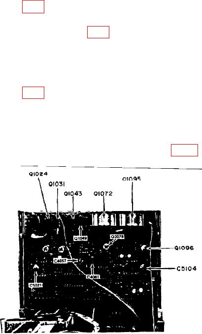
Figure 6. Deflection Amplifier - Adjustment and Test Point Locations.
15