
TB 9-6625-2134-24
NOTE
Units with 01 and 08 only: Press EXTERNAL MIXER
pushbutton to off.
(78) Push POWER switch to off.
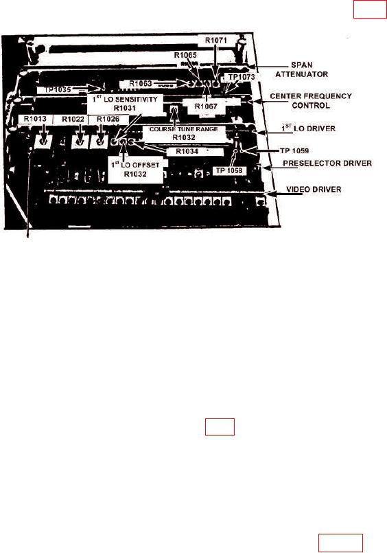
(79) If TI has option 01 and option 08, remove preselector driver board (fig. 8).
TP1011
Figure 8. 1st LO Balance and Span Adjustment and Test Points.
(80) Pull POWER switch to on.
(81) Press FREQUENCY RANGE pushbutton to 0-1.8 GHz.
(82) Position controls as listed in (a) through (e) below:
(a)
FREQUENCY SPAN/DIV control to 200 MHz.
(b)
TIME/DIV switch to MNL.
(c)
TRIGGERING FREE RUN pushbutton to on.
(d)
MANUAL SCAN control to midrange.
(e)
EXTERNAL MIXER pushbutton to on.
(83) Connect multimeter between TP1058 (fig. 8) and ground.
(84) Adjust FREQUENCY control for a readout of 0 MHz on crt as FREQUENCY
SPAN/DIV control is reduced to 5 MHz. Record multimeter indication.
(85) Adjust FREQUENCY control for a reading of 4.278 GHz on crt (switch
FREQUENCY SPAN/DIV control to 200 MHz to facilitate tuning, then reduce
FREQUENCY SPAN/DIV control to 5 MHz). Record multimeter indication.
NOTE
R1032 is located on the center frequency control board of figure 8.
18