
TB 9-6625-2134-24
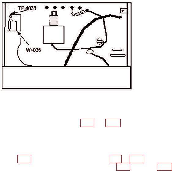
Figure 4. High Voltage Circuit Board (Early Version).
(18) Adjust INTENSITY control fully cw and MANUAL SCAN control fully ccw.
(19) Set TIME/DIV switch to MNL.
crt shield.
(21) Pull POWER switch to on. After TI stabilizes, press 2 dB/DIV VERTICAL
DISPLAY pushbutton.
(22) Press READOUT and DIGITAL STORAGE pushbuttons to off.
Pull POWER switch to on.
(25) Connect CAL OUT signal to RF INPUT.
(26) Position controls as listed in (a) through (i) below:
(a)
FREQUENCY control to 100 MHz.
(b)
FREQUENCY SPAN/DIV control to 10 MHz.
(c)
RESOLUTION BANDWIDTH control to MAX.
(d)
TIME/DIV switch to AUTO.
(e)
REFERENCE LEVEL control to -20 dBm.
(f)
NARRON VIDEO FILTER pushbutton to on.
(g)
MIN RF ATTEN dB control to 0.
(h)
10 dB/DIV VERTICAL DISPLAY pushbutton to on.
(i)
DIGITAL STORAGE pushbuttons to off.
13