Home
Download PDF
Order CD-ROM
Order in Print
Table 3. Harmonic Number (n) Versus Frequency Range
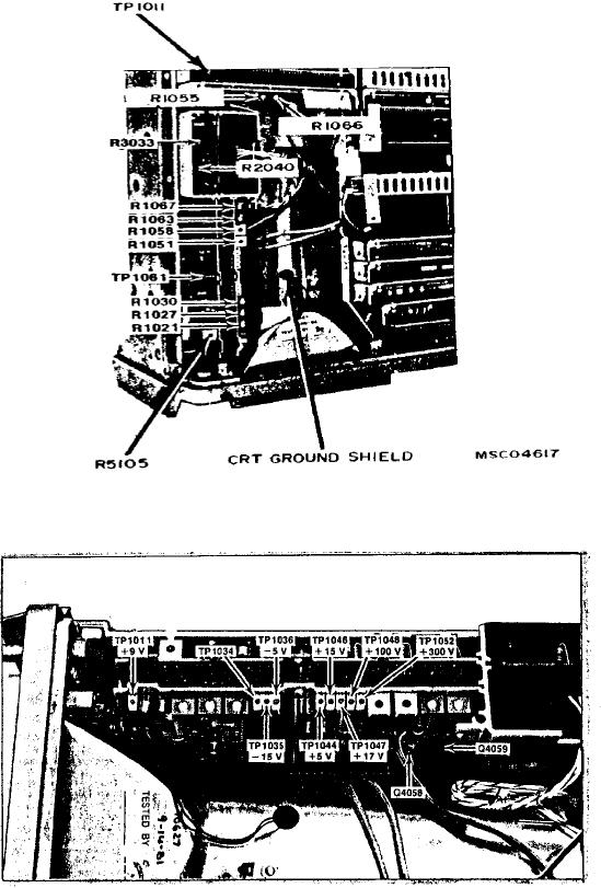
Figure 3. High Voltage Circuit Board (Later Version).
Calibration Procedure For Spectrum Analyzer An/Usm-489(V)1 (Type 492 W/Options 01, 02, 03, 08, And 21)
Page Navigation
6
7
8
9
10
11
12
13
14
15
16
TB
9-6625-2134-24
Figure
1.
Deflection
Amplifier,
High
Voltage Module,
and
Z-Axis/RF
Interface
Board -
Adjustment
Locations.
Figure
2.
Z-Axis
Test
Point
Locations.
11