
TB 9-6625-2190-24
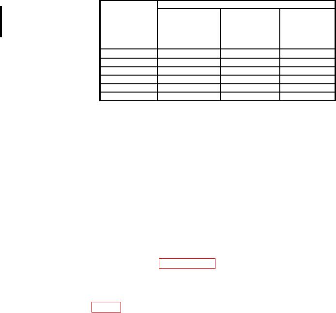
Table 7. Resistance
Calibrator
AN/PSM-45A
FLUKE 27 &
Test instrument
(FLUKE 27/FM)
27/AN
range settings
Error
Error
indications
indications
(%)
(%)
Settings
1
Ω2
Ω
0.42
0.42
190
320.0
kΩ
1.9 kΩ
0.31
0.26
3.200
kΩ
kΩ
0.31
0.26
32.00
19
kΩ3
kΩ
0.31
0.26
320.0
190
MΩ
1.9 MΩ
0.31
0.26
3.200
MΩ
MΩ
1.05
1.05
32.00
19
1
Use the REL function to compensate for offset at this range.
2
Set calibrator 2 wire Comp to ON.
3
Set calibrator 2 wire Comp to OFF.
b. Adjustments. No adjustments can be made.
12. Final Procedure
a. Deenergize and disconnect all equipment.
b. Annotate and affix DA label/form with TB 750-25.
CALIBRATION PROCESS FOR FLUKE 80K-6 HIGH VOLTAGE PROBE
13. Preliminary Instructions
a. The instructions outlined in paragraphs 13 and 14 are preparatory to the calibration
process. Personnel should become familiar with the entire bulletin before beginning
the calibration.
b. Items of equipment used in this procedure are referenced within the text by common
name as listed in table 2.
c. Unless otherwise specified, verify the result of the test and, whenever the test
requirement is not met, take corrective action. No calibration adjustments can be made on
the High Voltage probe.
d. Unless otherwise specified, all controls and control settings refer to the
handheld multimeter.