
TB 9-6625-2213-24
SELECT LOW PASS FILTER FROM TABLE 2.
1
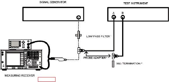
PART OF ACCESSORIES KIT, HEWLETT-PACKARD, MODEL 11570A.
2
Figure 1. Channel isolation - test equipment setup.
amplitude controls for 0 dBm indication on measuring receiver.
(3) Adjust TI FREQ RANGE-MHz switch so APC UNLOCKED light goes out and
setting includes measurement frequency.
(4) Set AMPLITUDE CHANNEL switch to A.
(5) Adjust signal generator amplitude controls for a TI meter indication of 0 dB.
(6) Set AMPLITUDE CHANNEL switch to B. The channel B signal amplitude will
not exceed -75 dBm (-80 dBm).
(7) Repeat (2) through (6) above for 600 and 1000 MHz.
+13 dBm indication on measuring receiver.
(9) Set TI FREQ RANGE-MHz switch so APC UNLOCKED light goes out and
setting includes measurement frequency.
(10) Set AMPLITUDE CHANNEL switch to A.
(11) Adjust signal generator amplitude controls for a TI meter indication of 1 V rms.
(12) Set AMPLITUDE CHANNEL switch to B. CHANNEL B vector voltmeter
residual noise indication will be equal to or less than 10 V.
(13) Repeat technique of (8) through (12) above for 100 and 300 MHz.
6