
TB 9-6625-2213-24
CAUTION
Do not exceed +10 dBm input to TI during this performance
check or damage to TI channel A probe may occur.
NOTE
Ensure AMPLITUDE CHANNEL switch is set to B.
(21) Set AMPLITUDE MV-RANGE-DB switch to 0 dB.
(22) Set variable attenuator to 0 dB.
(23) Set signal generator frequency controls to 30 MHz.
(24) Adjust FREQ RANGE-MHz control for a dial indication that includes 30 MHz.
(25) Adjust signal generator amplitude controls for an AMPLITUDE meter
indication of 0 dB.
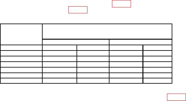
(26) Set variable attenuator to dB setting listed in table 4. The AMPLITUDE meter
will indicate within the limits listed in table 4.
Table 4. Voltage Ratio Accuracy
Variable
Test instrument
AMPLITUDE
attenuator
meter indications1
settings
(dB)
Min
Max
1
195.5
(193.0)
203.7
(205.0)
2
173.9
(172.0)
182.0
(183.0)
3
154.5
(152.0)
162.5
(164.0)
4
137.4
(135.0)
145.4
(147.0)
5
121.5
(120.0)
129.5
(132.5)
6
107.5
(106.0)
115.8
(118.0)
7
95.7
(93.8)
103.7
(106.0)
1Variable
attenuator calibration error must be included in AMPLITUDE meter limits.
(27) Repeat (26) above for remaining variable attenuator settings listed in table 4.
(28) Set variable attenuator to 0 dB.
(29) Set AMPLITUDE MV-RANGE-DB switch to 300 mV.
(30) Adjust signal generator amplitude controls for a 0 dB indication on
AMPLITUDE meter.
(31) Set variable attenuator to 10 dB.
11