
TB 9-6625-2213-24
(11) Adjust signal generator amplitude controls for TI full scale meter indication
(selected in (10) above).
(12) Configure measuring receiver to measure mV rms and set the RATIO function
on. If measuring receiver indications are not within the limits listed in table 3,
perform b below.
(13) Repeat (9) through (12) above for table 3 signal generator amplitude settings of -
17.4 to -66.9 dBm.
(14) Set signal generator RF output switch to OFF.
(15) Replace TI channel A probe with channel B probe in figure 2 equipment setup.
(16) Set AMPLITUDE CHANNEL switch to B position.
(17) Set signal generator RF output switch to ON.
(18) Repeat (3) through (13) above for remaining signal generator amplitude and
frequency settings listed in table 3 for CHANNEL B. If measuring receiver indications are
not within the limits listed in table 3, perform b below.
(19) Repeat (1) through (18) above for remaining signal generator amplitude and
frequency settings listed in table 3. If measuring receiver indications are not within the
limits listed in table 3, perform b below.
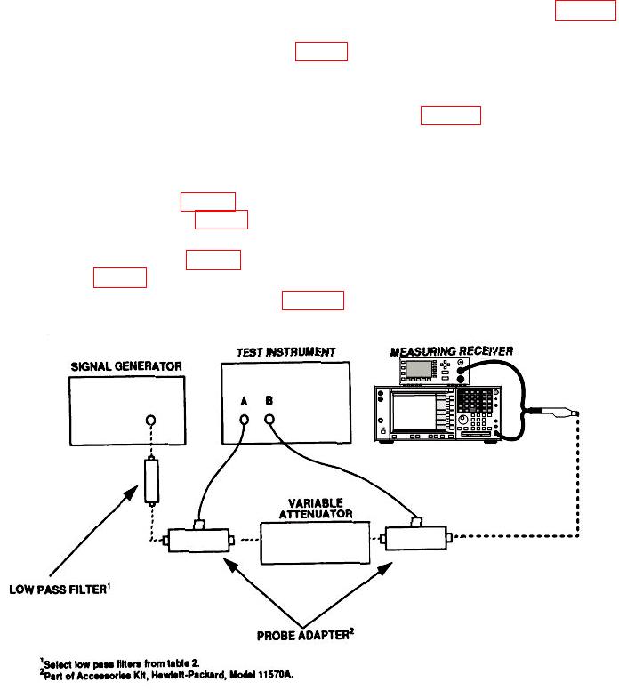
(20) Connect equipment as shown in figure 3.
Figure 3. Voltage ratio accuracy - equipment setup.
10