
TB 9-6625-2235-24
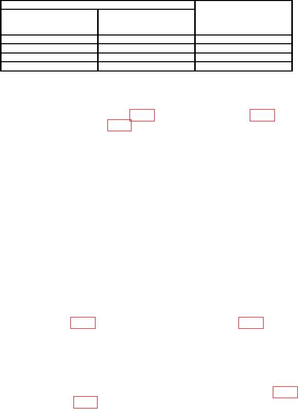
Table 6. Bandwidth Adjustments
Test instrument
RESOLUTION BW
FREQ SPAN/ DIV
Bandwidth at
switch
switch settings
5th graticule line
(kHz)
settings
above graticule baseline
3 MHz
500
5.4 to 6.6
300 kHz
50
5.4 to 6.6
100 kHz
20
4.3 to 5.7
30 kHz
5
5.2 to 6.8
(24) Disconnect CAL OUTPUT from INPUT 50Ω.
signal generator RF output to A9J1 (fig. 1).
(26) Adjust signal generator frequency to 301.4 MHz and RF output level controls
to -30 dBm.
controls to peak signal on TI crt.
(28) Adjust signal generator RF output level controls to position signal 7.1 divisions
above graticule baseline.
controls to peak signal on TI crt. Record signal generator frequency.
(30) Adjust REF LEVEL FINE control to position signal 7.1 divisions above
graticule baseline.
(31) Adjust signal generator frequency 1500 Hz below value recorded in (28) above.
Record signal generator frequency.
2332A) to position signal 5 divisions above graticule baseline (R).
(33) Increase signal generator frequency until TI trace peaks and then drops to 5
divisions above graticule baseline. Record signal generator frequency.
(34) Subtract the value recorded in (31) above from the value recorded in (33) above.
If the difference is not between 2800 and 3200 Hz, slightly readjust A8R72 (fig. 5 for SN
prefixed 2215A and below) (fig. 6 for SN prefixed 2332A) and repeat (29) through (34) until
the specified limits are achieved.
controls to peak signal on TI crt.
24