
TB 9-6625-2251-35
b. Select: CH1 COUPLING/INVERT and set: DC to on and 50Ω to off.
c. Connect oscilloscope calibrator SOURCE/MEASURE CHAN 1 output to TI CH 1
input connector, oscilloscope calibrator SOURCE/MEASURE CHAN2 output to TI CH 2
input connector. Rotate CH 1 VOLTS/DIV knob to set CH 1 for 2 mV indication in upper
left portion of crt.
d. Rotate HORIZONTAL A AND B SEC/DIV knob for 500 s indication on crt.
f. Rotate TRIGGER LEVEL knob as necessary to obtain a triggered display.
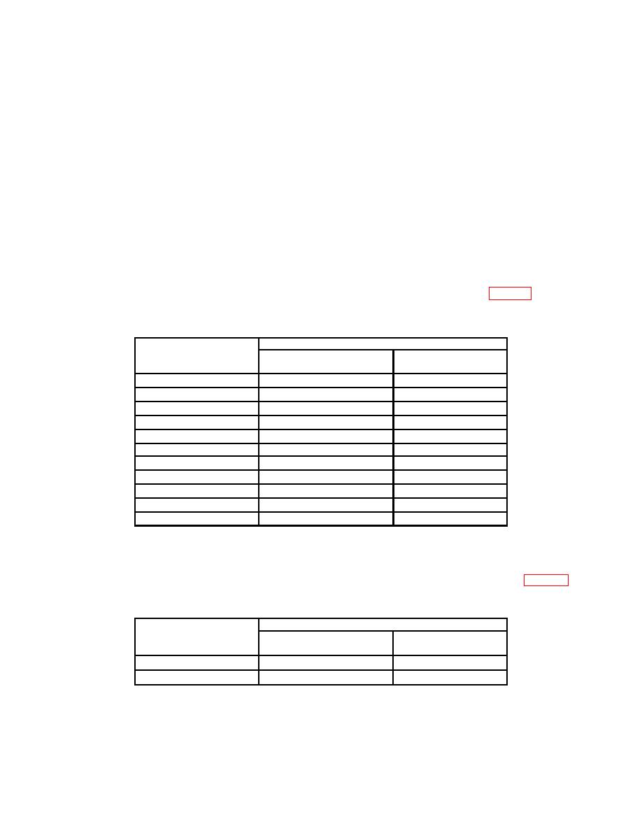
divisions displayed on TI crt. Err displayed on oscilloscope calibrator will be within 2.0
percent.
Oscilloscope calibrator
CH1 VOLTS/DIV
VOLTAGE
Err display
settings
settings
(%)
2mV
8mV
2.0
5mV
20 mV
2.0
10 mV
40 mV
2.0
20 mV
80 mV
2.0
50 mV
200 mV
2.0
100 mV
400 mV
2.0
200 mV
800 mV
2.0
500 mV
2V
2.0
1V
4V
2.0
2V
8V
2.0
5V
20 V
2.0
Select: VERTICAL MODE, set: CH 1 to off and set: CH 2 to on.
below.
Oscilloscope calibrator
CH2 VOLTS/DIV
VOLTAGE
Err display
settings
settings
(%)
2mV
8mV
2.0
5mV
20
mV
2.0
7
