
TB 9-6625-2259-24
(8) Repeat technique of (2) above for remaining TI LEVEL settings listed in table
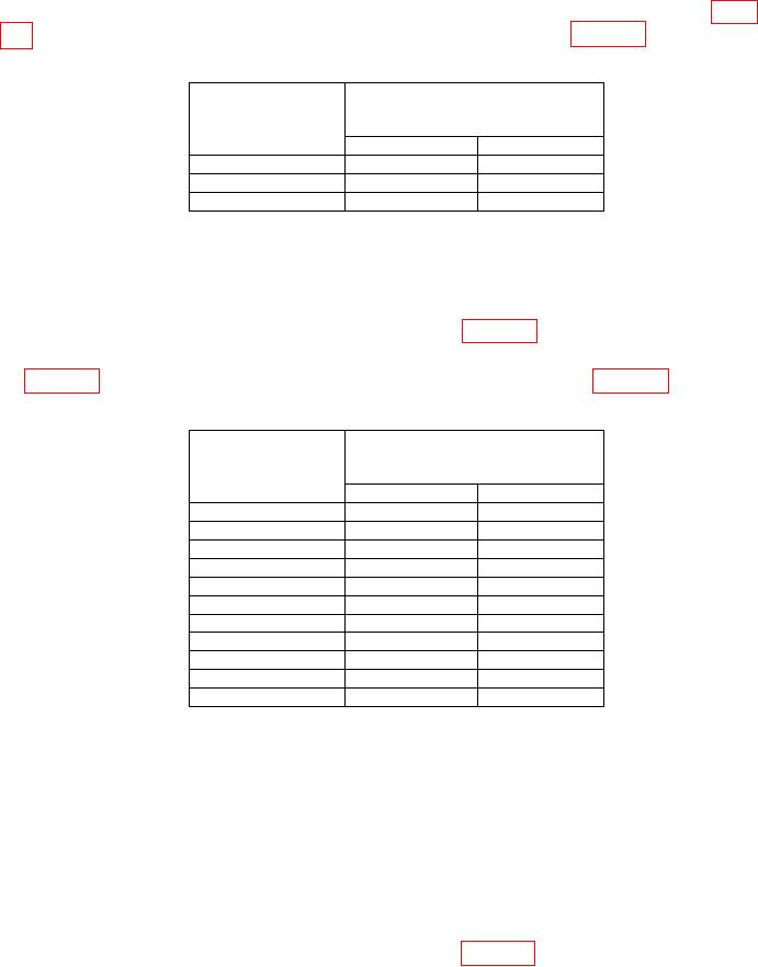
Table 11. Output Attenuator Test @ 1 GHz
Measuring receiver
Test instrument
indication
LEVEL settings
(dB)
(dBm)
Min
Max
13
10.4
15.6
10
7.4
12.6
3
1.4
5.6
(9) Press LEVEL key and adjust INCR-DECR control for 0.0 dBm indication on
measuring receiver.
(10) Using standard tuned level measurement techniques, verify the measuring
receiver indicates within limits specified in first row of table 12.
(11) Repeat technique of (9) and (10) above for remaining TI LEVEL settings listed
Table 12. Output Attenuator Test @ 1 GHz
Measuring receiver
Test instrument
indication
LEVEL settings
(dB)
(dBm)
Min
Max
0
-2.6
2.6
-10
-12.6
-7.4
-20
-22.6
-17.4
-30
-32.6
-27.4
-40
-42.6
-37.4
-50
-52.6
-47.4
-60
-62.6
-57.4
-70
-73.1
-66.9
-80
-83.1
-76.9
-90
-93.1
-86.9
-100
-103.1
-96.9
(12) Press LEVEL key and set LEVEL display to +10.0 dBm by pressing 10 with
DATA ENTRY keys and then by pressing GHZ/dBm/SEC DATA ENTRY key.
(13) Press FREQUENCY RANGE CW F1 key and set F1 M3 display to 18.000
GHz by pressing 18 with DATA ENTRY key and then by pressing GHz/dBm/SEC DATA
ENTRY key.
(14) Configure measuring receiver to measure frequency at and allow measuring
receiver to acquire carrier frequency.
(15) Configure measuring receiver to measure RF power.
Measuring receiver
indication will be within limits specified in first row of table 13.
27