
TB 9-6625-2322-24
(3) Disconnect the measuring receiver power sensor module from the POWER REF
output and connect it to the TI RF OUTPUT.
(4) Press TI keys as listed in (a) through (e) below:
SYSTEM, Reset.
(a)
OUTPUT off.
(b)
Frequency Control, F0, Edit F0, 2, and GHz.
(c)
OUTPUT on.
(d)
Level Control, L0, Edit L0, 0, and dB.
(e)
(5) Using measuring receiver and RF power techniques in Log Mode verify that the
measuring receiver indicates within tolerances listed in table 5.
(6) Using technique of (4) (e) set the TI to the remaining levels listed in table 5 and
repeat (5) above.
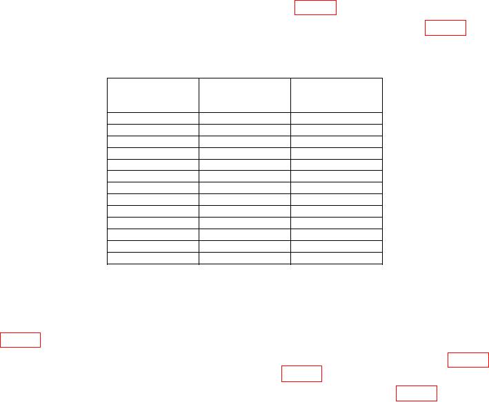
Table 5. 2 GHZ Output Level Test 1 dB Steps
Test instrument
Measuring
Measuring
output level
receiver indication receiver indication
(dB)
Min (dB)
Max (dB)
0
-1
1
-1
-2
0
1
0
2
2
1
3
3
2
4
4
3
5
5
4
6
6
5
7
7
6
8
8
7
9
9
8
10
10
9
11
11
10
12
(7) Press Level Control, L0, Edit L0, 0, and dB keys.
(8) Using standard tuned level measurement techniques, verify the measuring
receiver indicates within minimum and maximum limits for TI output level as listed in
table 6 below.
(9) Use the TI arrow key to decrement the output level 10 dB as indicated in table 6
verifying that the indication is within limits listed in table 6.
(10) Repeat (9) above for remaining TI output level settings listed in table 6.
10