
TB 9-6625-2340-24
CENTER FREQUENCY, 100, MHz.
(a)
FREQUENCY SPAN, 10, kHz.
(b)
RES BW, 1, kHz.
(c)
SCALE LIN.
(d)
REFERENCE LEVEL.
(e)
(9) Adjust TI DATA knob to position trace at (or just below) reference level (top)
graticule line.
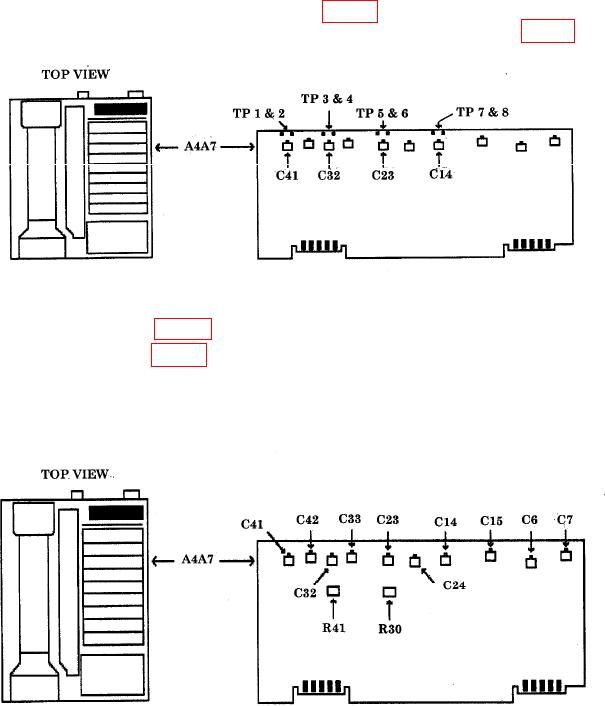
(10) Connect crystal filter bypass networks (fig. 10) between A4A7TP1 and A4A7TP2,
A4A7TP3 and A4A7TP4, A4A7TP5 and A4A7TP6, A4A7TP7 and A4A7TP8 (fig. 11).
Figure 11. A4A7 board - test points.
(11) Adjust A4A7C7 (fig. 12) for minimum signal peak amplitude.
(12) Adjust A4A7C6 (fig. 12) for best symmetry of signal.
(13) Repeat (11) and (12) above to ensure signal is nulled and adjusted for
best symmetry.
Figure 12. A4A7 board view 1.
24