
TB 9-6625-2340-24
INPUT B slope to positive.
(e)
INPUT A, AC/DC to DC.
(f)
INPUT A, 50 /1M to 1M .
(g)
TRIGGER LEVEL set A to 0.7 V.
(h)
INPUT A, 1X/10X to 10X.
(i)
HOLD OFF to ON.
(j)
(3) Press TI keys as listed in (a) through (d) below:
2-22 GHz.
(a)
CENTER FREQ, 500 MHz.
(b)
SPAN, 0 Hz.
(c)
SWEEP TIME, 20, mSEC.
(d)
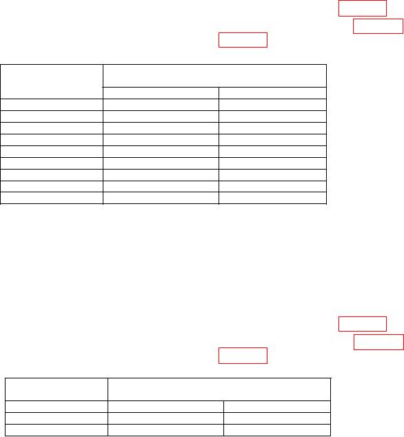
(4) Electronic counter will indicate within limits specified in first row of table 22.
(5) Repeat (3) (d) and (4) above for remaining sweep time settings in table 22.
Electronic counter will indicate within limits specified in table 22.
Table 22. Sweep Time Accuracy
Electronic counter
Test instrument
displayed reading
sweep time
Min
Max
20 ms
18 ms
22 ms
30 ms
27 ms
33 ms
50 ms
45 ms
55 ms
70 ms
63 ms
77 ms
90 ms
81 ms
99 ms
110 ms
99 ms
121 ms
170 ms
153 ms
187 ms
200 ms
180 ms
220 ms
2s
1.8 s
2.2 s
(6) Set electronic counter for a gate time of 10 sec.
(7) Press TI MARKER NORMAL key.
key to place marker at second vertical graticule line.
(8) Use TI
(9) Press TI SWEEP TIME, 20, and SEC keys.
(10) Press electronic counter MEASUREMENT RESTART.
(11) Press TI TRACE A CLEAR-WRITE key and allow TI to complete sweep.
(12) Electronic counter will indicate within limits specified in first row of table 23.
(13) Repeat (9) through (11) above for remaining sweep time setting in table 23.
Electronic counter will indicate within limits specified in table 23.
Table 23. Sweep Time Accuracy
Test
Electronic counter
instrument
displayed reading
Sweep time
Min
Max
20 s
18 s
22 s
200 s
188 s
222 s
b. Adjustments. None.
53