
TB 9-6625-2341-24
(k) (For original settings, SCOPE mode needs to be selected. Change to
SCOPE mode now? (F1) YES then (F1) CLOSE) or (if all ScopeMeter settings have been
set to original setting then (F1) CLOSE), which will display/highlight RESET SCOPE.
(l) (F1) CLOSE which will display/highlight RESET MENU.
(m) (F1) CLOSE which will display/highlight CONTR.
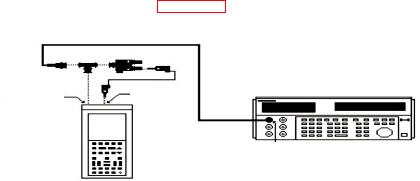
(2) Connect equipment as shown in figure 1.
CALIBRATOR
CH A
COM
SOURCE/MEASURE
EXT TRIG CHAN 1
TI
Figure 1. Scope vertical gain input A.
(3) Press pushbutton sequence as listed in (a) through (d) below:
(a) Disable "Input B" by pressing (i) through (vii) below:
(i)
INPUT B to display/highlight DISPLAY INPUT B.
(ii) (F1) MORE INPUT B.
(iii) Toggle
or
to display/highlight INPUT B.
(iv) (F5) SELECT ITEM.
(v) Toggle
or
to display/highlight off.
(vi) (F5) SELECT ITEM.
(vii) (F1) CLOSE.
(b) Change "Input A" probe setting to 1:1 by pressing (i) through (ix) below:
(i)
INPUT A to display/highlight DISPLAY INPUT A.
(ii) (F1) MORE INPUT A.
(iii) Toggle
or
to display/highlight PROBE A MENU.
(iv) (F5) SELECT ITEM which will display/highlight PROBE on INPUT A.
(v) (F5) SELECT ITEM which will display/highlight (1:1, 10:1, 100:1, 1000:1 , etc.).
(vi) Toggle
or
to display/highlight 1:1.
(vii) (F5) SELECT ITEM which will display/highlight PROBE on INPUT A.
(viii)(F1) CLOSE which will display/highlight INPUT A.
(ix) ( F 1 )C LO SE w hi c h wi l l d isp l a y/ h i g hl i g h t D I SP L A Y INPUT A.
(c) Auto to manual range by toggling (mV RANGE V) on left side, under
INPUT A pushbutton to display/highlight A 5mVDC 1:1.