TB 9-6625-2343-40
(b) DATA SPCL.
(c) DATA 49., MEASUREMENT S, 2.
(d) DATA SPCL.
(39) Multiply TI indication by number recorded in (34) above.
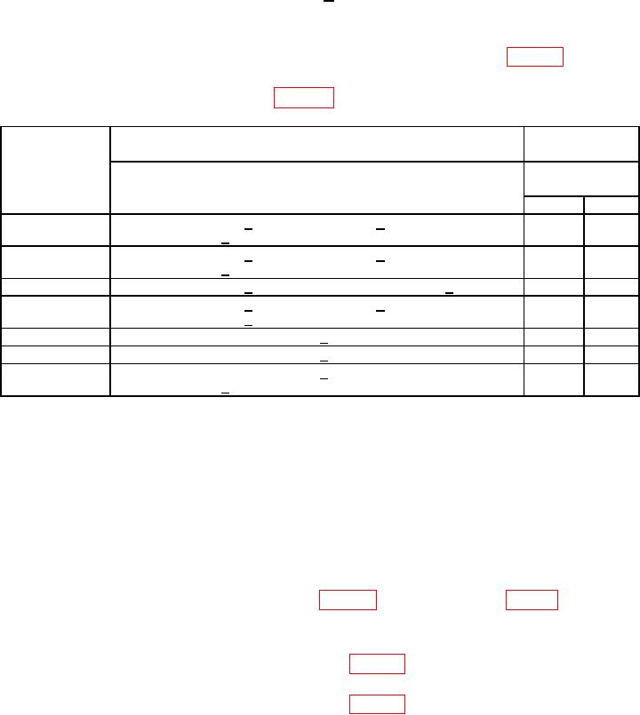
(40) The computed result should be within limits specified in first row of table 28 below.
(41) Repeat technique of (37) through (39) above using signal generator No. 1 output
levels and TI special functions listed in table 28 below.
Table 28. IF Gain Accuracy
Signal
Calculated
Test instrument
result
output level
decrease
Special function
Limit
(dB)
data key strokes
Min
Max
5
0.3, MEASUREMENT S, 4, MEASUREMENT S, 3, SPCL, 49.,
0.944
1.059
MEASUREMENT S, 2, SPCL
0.944
1.059
5
0.3, MEASUREMENT S, 4, MEASUREMENT S, 1, SPCL, 49.,
MEASUREMENT S, 2, SPCL
5
0.3, MEASUREMENT S, 47, SPCL, 49., MEASUREMENT S, 2, SPCL
0.944
1.059
0.944
1.059
5
0.3, MEASUREMENT S, 4, MEASUREMENT S, 4, SPCL, 0.391, SPCL,
49., MEASUREMENT S, 2, SPCL
0
0.392, SPCL, 49., MEASUREMENT S, 2, SPCL
0.944
1.059
0
0.394, SPCL, 49., MEASUREMENT S, 2, SPCL
0.944
1.059
0
0.390, SPCL, 0.3, MEASUREMENT S, 31, SPCL, 49.,
0.944
1.059
MEASUREMENT S, 2, SPCL
(42) Reduce all outputs to minimum and disconnect equipment setup.
b. Adjustments. None
18. Power Supply
a. Performance Check
NOTE
Do not perform power supply adjustments if all other
parameters are within tolerance.
and set multimeter to read V dc.
(2) If multimeter indication is not between 14.99 and 15.01 V dc perform b below.
(3) Move positive lead from TP3 to TP4 (fig. 20) and verify multimeter indicates
between -15.2 and -14.8V dc.
(4) Move positive lead from TP4 to TP5 (fig. 20) and verify multimeter indicates
between 4.9 and 5.2 V dc for serial number 2305A to 2616A and between 5.1 and 5.2 V dc
for serial number 2618A and above.

