
TB 9-6625-975-24
9. Voltage Check
a. Performance Check
(1) Connect multimeter positive dc terminal to GROUND terminal and common
terminal to GUARD or SHIELD terminal.
(2) Turn generator crank rapidly cw until clutch slips. If multimeter does not
indicate between 475 and 525 V dc (450 and 550 V dc for ZM-21( )/U having electronic
controller; 524 and 556 V dc for Biddle Model 210359), perform b below.
b. Adjustments
(1) Remove TI chassis from case and remove chassis cover.
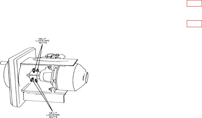
(2) If voltage is too high, loosen the four clutch SELF LOCKING NUTS (fig. 1)
equally, between the clutch drive hub and clutch driven hub. Repeat a (2) above until
correct voltage is obtained.
(3) If voltage is too low, tighten the four clutch SELF LOCKING NUTS (fig. 1)
equally. Repeat a (2) above until correct voltage is obtained.
Figure 1. Ohmmeter clutch voltage adjustment.
NOTE
Adjustment is not provided for ZM-21( )/U having the electronic
controller.
10. Resistance Measurement
a. Performance Check
(1) Connect resistance standard no. 1 HI terminal to TI LINE terminal and
resistance standard LO terminal to TI GROUND terminal.
(2) While rotating crank, adjust resistance standard for an indication of 100 kilohms
on meter. Resistance standard will indicate between 95 and 105 kilohms.