
TB 9-4920-467-24
(2) Set the resistance standard to 1100.00 Ω.
Allow the circuit to stabilize for
2 minutes.
(3) Select and activate OK. The TI will measure the resistance.
When the
measurement is completed, a second on-screen instruction is displayed.
Set the resistance standard to 900.00 Ω. Select and activate OK.
(4)
(5) When both resistance measurements are complete, the alignment progress bar
will show 100%. The TI will calculate the alignment constants. The TI will enter a live-
reading performance check mode.
(6) Press the TI ETTS BrainPak left Encoder knob to save the alignment
constants.
Repeat paragraph 16 a above.
(7)
17. Jrt
a.
Performance Check
(1) Select and activate Jrt from the Circuit menu on the UxValidator.
Jrt will
appear in the Circuit field.
(2)
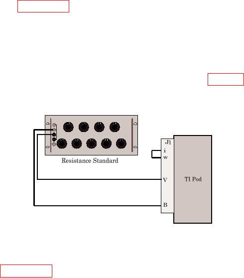
Connect resistance standard to TI ETTS Pod as shown in figure 26.
(3)
Select and activate Test from the POD Alignment screen on the UxValidator.
Figure 26. Jrt Connection.
NOTE
Annotate readings in steps (4) through (6) below for use in
paragraph 18 below.
(4) Set the resistance standard to 800.00 Ω. If TI reading on UxValidator does not
indicate between 799 and 801 Ω, perform b below.
(5) Set the resistance standard to 850.00 Ω. If TI reading does not indicate between
849 and 851 Ω, perform b below.