
TB 9-4931-488-24
(7) Adjust pulse generator for a 1.000 V rms output.
(8) Adjust AM control for 90% modulation (9 on 0 - 10 scale) as indicated on TI
meter. The measuring receiver should indicate between min and max limits listed in
(9) Repeat technique of (8) above for TI meter indications listed in table 23. The
measuring receiver should indicate as specified.
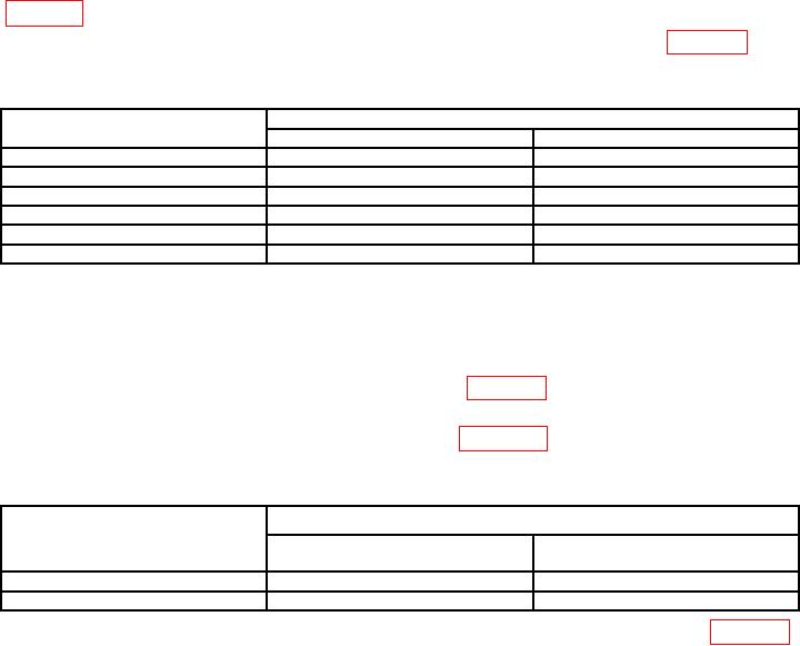
Table 23. OPT 004 AM Accuracy.
Measuring receiver % AM indications (%)
Test instrument
meter indications (%)
Min
Max
90
83.6
96.5
70
64.7
75.4
50
45.8
54.3
30
26.9
33.2
20
17.4
22.6
10
7.95
12.1
(10) Press LEVEL VOLTS pushbutton. Set OUTPUT LEVEL 10 dB switch to
0 dBm. Adjust 1 dB switch and OUTPUT LEVEL vernier control for a -7dB indication on
TI meter.
(11) Adjust AM control for a 50% AM depth indication on measuring receiver. The
modulation distortion should be within limits listed in table 24.
(12) Repeat technique of (10) and (11) above for TI meter dB indications and
measuring receiver % AM indications listed in table 24. The measuring receiver
modulation distortion indications should be as specified.
Table 24. OPT 004 AM Distortion.
Measuring receiver
Test instrument
Modulation distortion
meter indications (dB)
% AM indications (%)
indications (< %)
-7
50
1
-7
90
3
(13) Reduce all outputs to minimum, then reconnect equipment as shown in figure 6,
but leave TI RF OUTPUT disconnected and remove top cover to access switch A26A8S1.
(14) Position controls as listed in (a) through (i) below.
(a)
AM X10% pushbutton pressed.
(b)
AM switch to AC.
(c)
FM switch to OFF.
(d)
RANGE MHz switch to 128 - 64.
(e)
FREQUENCY TUNE control for FREQUENCY MHz display indication of 113 MHz.
(f)
AM control fully ccw.
(g)
OUTPUT LEVEL 10 dB switch to 0 dBm.
(h)
OUTPUT LEVEL 1 dB switch to 0.
(i)
OUTPUT LEVEL vernier to CAL.
30