
TB 9-4931-488-24
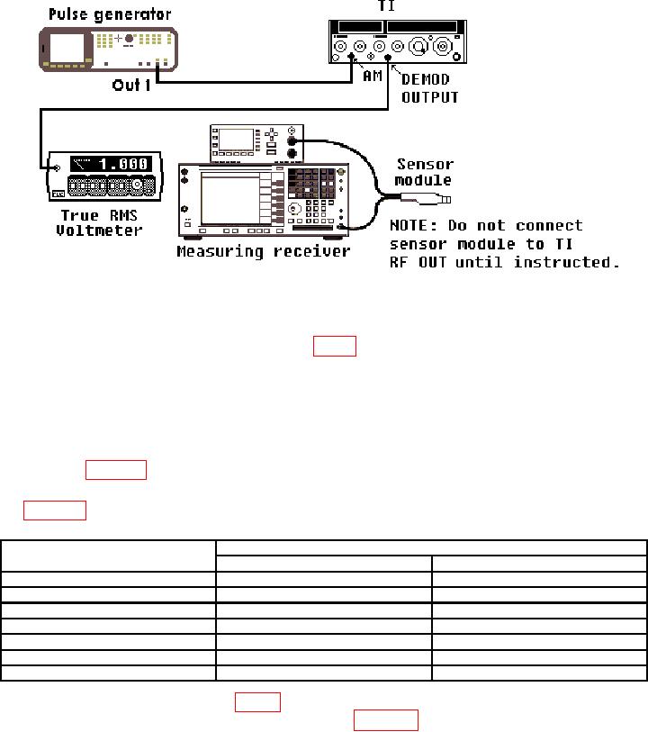
Figure 6. Demodulated Output Accuracy - Equipment Setup.
(15) Press measuring receiver PRESET. Connect measuring receiver sensor module to
TI RF OUT and set to measure frequency.
(16) Note position of switch A26A8S1 (fig. 2) and set to AC position
(17) Adjust pulse generator for a 0.718 V, 120 Hz output signal. If necessary switch
RF OUT ON.
(18) Adjust AM control for a true rms voltmeter indication of 1.000 V ac (use pulse
generator adjustment knob to fine adjust).
(19) Set measuring receiver to measure AM depth. If measured results are not as
specified in table 25 perform b below.
(20) Repeat technique of (18) and (19) above for true rms voltmeter indications listed
in table 25. If results are not as specified; perform b below.
Table 25. Demodulated Output Accuracy (A26A8Sl set to AC).
True rms voltmeter
Measuring receiver % AM indications (%)
Indications (V Ac)
Min
Max
1.000
19.6
20.4
1.500
29.4
30.6
2.000
39.2
40.8
2.500
49.0
51.0
3.000
58.8
61.2
3.500
68.6
71.4
4.000
78.4
81.6
(21) Set switch A26A8S1 (fig. 2) to DC position. Repeat technique of (18) and (19)
above for true rms voltmeter indications listed in table 26. If measuring receiver does not
indicate within limits specified, perform b below.
31