
TB 9-6130-285-24
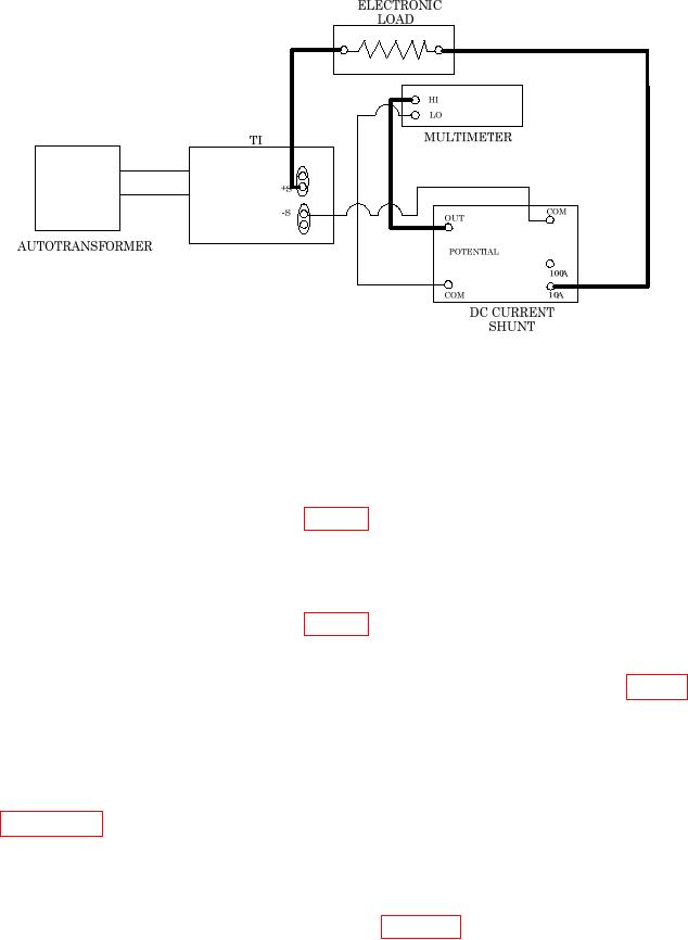
Figure 3. Load and line regulation (constant current).
(9) If using electronic load Astec America Inc., EL750B, set the static current
control fully CCW until TI front panel display indicates FS amps and ensure CC enunciator
is illuminated. If using electronic load Transistor Devices, DLP-130-50-2500, release the
SHORT CIRCUIT switch.
(10) Adjust the autotransformer until the meter indicates 105 V ac, unless minimum
line voltage is otherwise specified in table 1.
(11) Divide the multimeter indication by the DC current shunt certified resistance
and record results.
(12) Adjust the autotransformer until the meter indicates 125 V ac, unless maximum
line voltage is otherwise specified in table 1.
(13) Repeat step (11) above.
(14) The difference between step (11) and (13) above must be within table 1 Line
Load Regulation CC limits.
(15) Set electronic load DC circuit breaker to Off.
(16) Using TI front panel controls, program voltage and current outputs for 0.
b. Adjustments. No adjustment can be made for 1791; for all others see
18. Ripple and Noise Calibration
a. Performance Check
(1) Connect equipment as shown in figure 4. To measure constant current rms
ripple, connect the True RMS Voltmeter. To measure constant current p-p ripple connect
the oscilloscope.