
TB 9-6625-100-24
(2) Set the multimeter as listed in (a) through (d) below.
(a) OHMF.
(b) OCOMP on.
(c) NPLC 100.
(d) RANGE AUTO.
(3) Place calibration resistor labeled SHORT in the remote test fixture.
(4) Allow multimeter indication to stabilize then record residual (zero) resistance.
(5) Remove calibration resistor labeled SHORT from the test fixture.
(6) Place first calibration resistor from table 3 in the test fixture.
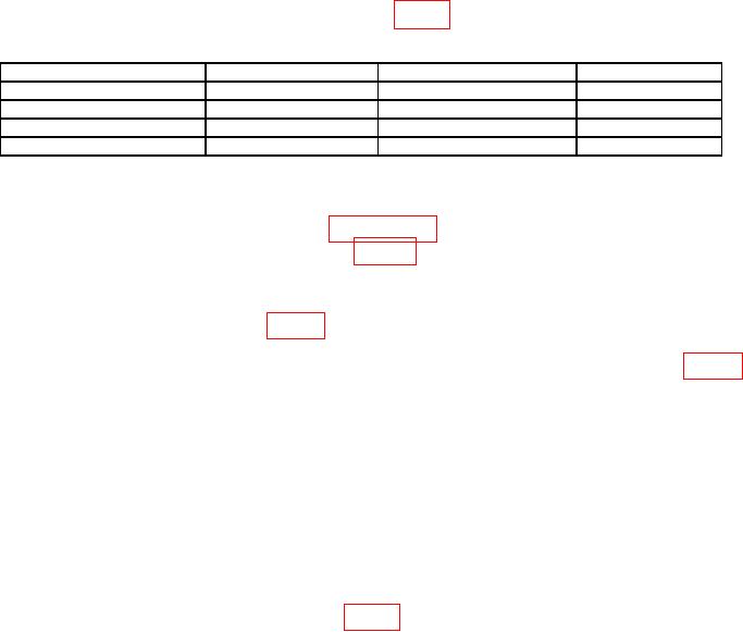
Table 3. Calibration Resistor Characterization and Acceptance.
Calibration resistor (Ω)
Min (Ω)
Max (Ω)
Present measured value
24.9000
24.8751
24.9249
374.000
373.626
374.374
5.97000 k
5.96403 k
5.97597 k
95.3000 k
95.2047 k
95.3953 k
(7) Allow multimeter indication to stabilize. Subtract residual (zero) resistance
from indicated value. Record this value (6 digits of resolution) as the present measured
value of the calibration resistor for use in paragraph 9. Ensure that the calibration resistor
also meets the Min/Max acceptance limits in table 3.
NOTE
Calibration resistors that have drifted outside the Min/Max
acceptance limits in table 3 must be replaced.
(8) Repeat technique of (6) and (7) above for remaining calibration resistors in table 3.
(9) Disconnect equipment set-up.
8. Frequency Accuracy
a. Performance Check
NOTE
Throughout this entire procedure, unless specifically stated,
disregard the status of the GO/NO-GO lamp.
(2) Set TI to first frequency value in table 4 by completing (a) through (d) below.
(a) EXTERNAL BIAS to OFF.
(b) FUNCTION (if necessary) to select ENTER.
(c) Press 4 = SHIFT SPECIAL 1.
(d) Press . 0 1 2 = SHIFT FREQUENCY.